- Semiconductor BusinessHOME
- Products and Services of Macnica,Inc.
-
technical information

-
Events and Seminars
- Handling Manufacturer
- Support
- Inquiry
- Click here to purchase products
- Semiconductor business e-mail magazine registration
![]()
![]() Narrow down by specifying conditions
Narrow down by specifying conditions
現在2147件がヒットしています。check


hello.
My name is Intel F. Hanako and I provide technical support for Intel® FPGA products at Macnica.
For RTL-level simulation of designs for Intel FPGAs, use third-party tools (EDA tools) like ModelSim ®– Intel ® FPGA Edition.
If your design includes IP created in Quartus ® Prime, you need to generate a simulation model for the IP and set up a simulation library for the model.
In other words, the user must know the following three points.
✔ Which file is the simulation model for the IP you are using?
✔ Which simulation library corresponds to the simulation model?
✔ How to use the library in EDA tools
The following content introduces how to simplify the handling of these items.
|
Quartus Prime Standard Edition Quartus Prime Lite Edition |
Quartus Prime Pro Edition |
| Let NativeLink solve your FPGA function simulation |
Designs containing IP generated by Quartus ® Prime Pro Edition |
These methods automatically integrate the contents of the simulation script file msim_setup.tcl for all IPs used in the design, and are highly recommended!
(And NativeLink will script your non-IP user design and testbench files together.)
The content information above should cover all your work,
This time, I will introduce how to manually edit this msim_setup.tcl and how to run the edited script file with ModelSim.
(Because it is a rather troublesome task, it is for advanced users. Please be careful.)
Target environment
| Quartus Prime |
Quartus Prime Pro Edition Quartus Prime Standard Edition Quartus Prime Lite Edition |
| Simulation tool (Note 1) |
ModelSim PE / ModelSim SE / Questa ModelSim - Intel FPGA Edition (includes Starter Edition) |
Note 1: For the supported version of each tool, please check the release notes of the version of Quartus Prime you are using.
Note 2: All schematic designs (.bdf) must be converted to HDL.
<Reference FAQ> Q: I want to simulate a design with a schematic in ModelSim, but it doesn't work.
Generate msim_setup.tcl and simulation model
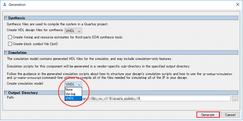
If the module created by Platform Designer or IP Catalog in the design is "started based on Platform Designer GUI", there is "simulation model generation option" at Generate, so select the language and then generate Please run the. (If not selected, no simulation model or msim_seutp.tcl file will be generated and simulation will not run.)
A simulation model and msim_setup.tcl file are automatically generated for IP created in the Wizard format in the IP Catalog.
Also, some IPs created in the IP Catalog do not have their own simulation models generated (for example, ALTLVDS_RX/TX, ALTPLL, RAM: 2-PORT, etc.). In that case, msim_setup.tcl will not be generated either. So make your own scripts.
Basic configuration of msim_setup.tcl
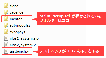
The msim_setup.tcl file is generated in the following folder after executing module generate. (with exceptions)
| IP module created with IP Catalog | <ip_name>_sim folder ➤ in mentor folder |
| Modules created with Platform Designer | In the <ip_name> folder ➤ simulation folder ➤ mentor folder |
Tcl scripts consider lines starting with a "#" mark to be commented out.
Each section in the msim_setup.tcl file is commented out with a # at the beginning of each section to summarize what it does.
Here, let's take a look at the content of the commented-out requirements (a typical basic configuration).
|
Requirement (comment part) |
Overview |
|
# Initialize variables # Initialize simulation properties - DO NOT MODIFY! |
Describes how to set variables, such as Quartus Prime installation folder path and IP generation folder path. |
| # Copy ROM/RAM files to simulation directory | Instructions are provided to copy the required memory initialization files to the simulation folder. |
|
# Create compilation libraries # Compile device library files |
Contains instructions for creating and compiling various libraries required for simulation. |
| # Compile the design files in correct order | Contains instructions to perform IP compilation. |
|
# Elaborate top level design # Elaborate the top level design with novopt option |
Contains instructions for loading the design. *Some people refer to "loading the design" as "running the simulation". * ModelSim – Intel FPGA Edition users should use "# Elaborate the top level design with novopt option". |
|
# Compile all the design files and elaborate the top level design # Compile all the design files and elaborate the top level design with –novopt |
Instructions are provided to compile all the necessary design files and run the simulation all at once. * For ModelSim – Intel FPGA Edition users, please use "# Compile all the design files and elaborate the top level design with –novopt". |
*This is an example. Not all msim_setup.tcl have the same configuration.
Create and edit msim_setup_edit.tcl
Since msim_setup.tcl is an auto-generated script specifically for the IP, the IP itself is designated as the top module and lacks information when applying a user-created design file or testbench.
Edit msim_setup.tcl to apply it to your project design.
[Note]
It is recommended to use msim_setup.tcl in the generated folder location.
If you move it to another folder and use it, the path environment of the default library and IP file will be broken, so
Correct the variable setting and use it according to the file path environment to be used.
Also, if you are using multiple IPs, you will have multiple msim_seup.tcl. Manually merge all necessary parts of msim_setup.tcl.
1) Duplicate msim_setup.tcl and rename it
Duplicate msim_setup.tcl for editing and rename the file.
Here, msim_setup_edit.tcl.
2) Add your design and testbench
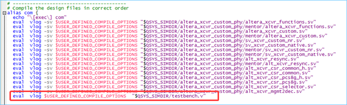
① Open msim_setuip_edit.tcl and search for "alias com".
(This is where the instructions for ModelSim to compile the design files are written.)
(2) Add the following execution command to compile the user's design file and testbench.
The compile execution commands are vcom for VHDL and vlog for Verilog HDL respectively.
<Basic structure of command>
[VHDL] eval vcom $USER_DEFINED_COMPILE_OPTIONS "file path"
[Verilog] eval vlog $USER_DEFINED_COMPILE_OPTIONS "file path"
The file path can be absolute or relative.
For example, if the storage folder of the Verilog HDL testbench (testbench.v) has the configuration shown below (a folder one level above msim_setup.tcl)
eval vlog $USER_DEFINED_COMPILE_OPTIONS "./../testbench.v"You can also click here (↓).
eval vlog $USER_DEFINED_COMPILE_OPTIONS "$QSYS_SIMDIR/testbench.v"[Note]
In msim_setup_edit.tcl the variable "QSYS_SIMDIR" is set as set QSYS_SIMDIR "./../".
It should look like this.
Similarly, add the compile command for the user design required for simulation.
If you want to add IP information other than the IP used in msim_setup_edit.tcl being edited, in the following comment part of msim_setup.tcl for the original IP
Copy the execution contents, paste it to various places in the destination msim_setup_edit.tcl, and merge the scripts.
Below is a reference to copy and paste.
# Copy ROM/RAM files to simulation directory
# Create compilation libraries
# Compile device library files
# Compile the design files in correct order
3) Change the target design to load the design to Testbench
By default, msim_setup_edit.tcl treats IPs and modules created with Platform Designer as top designs.
So make the testbench the top module.
There are two ways to change it. Please respond either way.
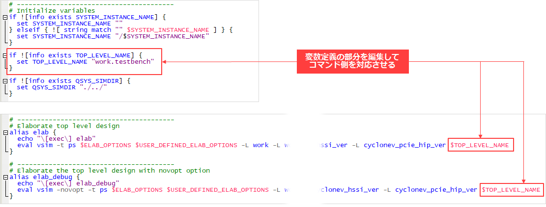
<Method 1: Edit the vsim command part directly>
① Search for the "vsim" command. (This is where the instructions for executing the design load are written.)
(2) Change the variable "$TOP_LEVEL_NAME" at the end of the vsim command to "work.testbench name".
for example
Change before
eval vsim -novopt -t ps <途中省略> $TOP_LEVEL_NAMEAfter change
eval vsim -novopt -t ps <途中省略> work.testbenchIt should look like this.

<Method 2: Edit the declaration of the variable "$TOP_LEVEL_NAME">
① Search for "set TOP_LEVEL_NAME". (Towards the # Initialize variables section.)
(2) Change the module name in double quotation marks to the module name of the testbench.
for example
set TOP_LEVEL_NAME "work.testbench"It should look like this.
4) Overwrite msin_setup_edit.tcl and reflect the edited contents
[Note]
Each msim_setup.tcl is overwritten and updated when the IP or Platform Designer design is changed and re-generated.
Therefore, please edit msim_setup_edit.tcl with the updated contents each time.
That's all for editing msim_setup_edit.tcl.
Run msim_setup_edit.tcl after editing in ModelSim
Run the edited msim_setup_edit.tcl in ModelSim.
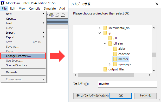
① Start ModelSim and select File menu ➤ Change Directory (or cd command).
Move to the folder where the edited msim_setup_edit.tcl is saved.
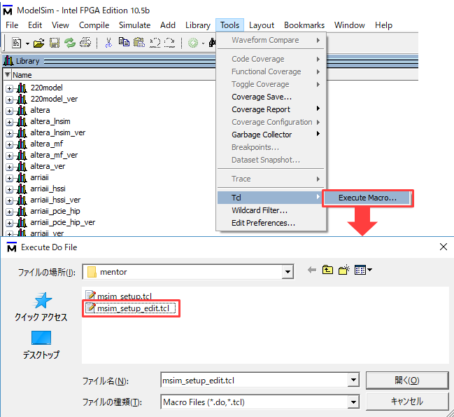
(2) Select and execute the script file by Tools menu ➤ Tcl > Execute Macro… (or do command).
③ The script is loaded and the command line alias is displayed in the Transcript window.
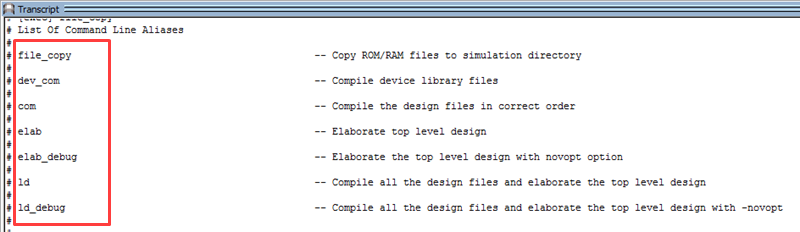
④ Enter the alias to be executed in the Transcript window.
For example, if you want to compile the library and design files and load the design at once,
Enter "ld" or "ld_debug".
[Note]
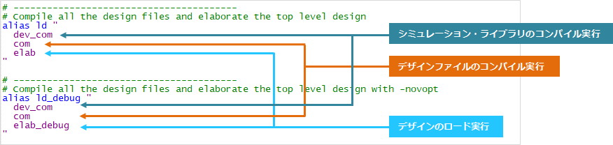
ld and ld_debug will do whatever is defined in msim_setup_edit.tcl with alias xxx "…".
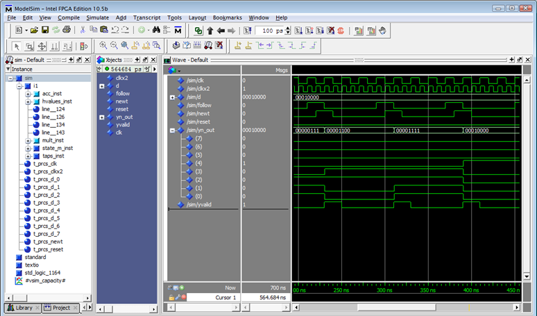
⑤ After loading the design with ld or ld_debug, add the signal to be observed to the Wave window and start the simulation as usual.
Examine the waveform displayed in the Wave window.

Hanako's point♪
After executing the ld or ld_debug alias, you can also add (register) the waveform to the Wave window and run the simulation.
Let's turn it into a command!
Then, a series of simulation tasks can be executed at once in a script, which is very convenient.
(1) Create a new script file. Here we call it sim_all.do and save it in the same folder as msim_setup_edit.tcl.
(2) Open it with a text editor and write the following contents.
・ msim_setup.tcl execution command (do command)
・ Run ld or ld_debug alias
・ Command to add testbench port to Wave window (add wave)
・ Simulation execution command (run command)
For example,
do E:/fpga_design/ip/pll_sim/mentor/msim_setup_edit.tcl ld_debug add wave * run 500ms③ Start ModelSim and move to the folder where sim_all.do is located by File menu ➤ Change Directory.
④ Select and execute sim_all.do from Tools menu ➤ Tcl > Execute Macro….
(5) All of the operations in (2) above are executed. Examine the waveform displayed in the Wave window.
This time, I saved msim_setup_edit.tcl and sim_all.do in the folder where msim_setup.tcl is saved for easy understanding, but if the paths of simulation libraries, simulation models, design files, etc. are consistent, the script file is It doesn't matter where you save it.
Create your own original scripts and run simulations more efficiently.
Script file description
Here are some of the commands used in msim_setup.tcl.
|
command |
Overview and example |
| vlib | create a library Example: vlib rtl_work |
| vmap |
Mapping the logical library name to the path of the library on the filesystem 例: vmap work rtl_work |
| vlog |
Compile Verilog and SystemVerilog files into libraries Example: vlog -work work ./sample.v |
| vcom |
Compile VHDL files into libraries For example: vcom -work work ./sample.vhd |
| vsim |
load the design Example: vsim work.sample_tb |
| add wave |
Add Selected Signals to Wave Window Example: add wave * |
| view |
display the specified window Example: view structure |
| run |
run the simulation Example: run 500ms |
You can also add or edit commands in the generated script file and use it. Add # at the beginning of the line to comment out.
For more information on commands and command options, see the ModelSim, Questa Command Reference Manuals.
Click here for recommended articles/materials
Let's generate and run a simulation script file for ModelSim ®
Let NativeLink solve your FPGA function simulation
How to Functionally Simulate a Design with Quartus ® Prime Pro Edition Generated IP in ModelSim
ModelSim ®- Intel ® FPGA Edition - How to RTL Simulation