- Semiconductor BusinessHOME
- Products and Services of Macnica,Inc.
-
technical information

-
Events and Seminars
- Handling Manufacturer
- Support
- Inquiry
- Click here to purchase products
- Semiconductor business e-mail magazine registration
![]()
![]() Narrow down by specifying conditions
Narrow down by specifying conditions
現在2183件がヒットしています。check

Hello. I'm Tonpa, a new FAE.
I joined Macnica as a new graduate and learned about circuit design and implementation while experiencing manufacturing through production training. When I was a student, I majored in organic chemistry, and I started with no knowledge of electricity and electronics, so I often struggled.
Therefore, in this article, I will introduce what I learned about circuit design and implementation while experiencing manufacturing through manufacturing training. Last time, we introduced the types of DC/DC converters, but this time we will introduce how to select DC/DC converters and inductors, which are peripheral components.
Wrong selection of DC/DC converter
Suddenly, I once failed in selecting a DC/DC converter.
I selected the LTC1877 as a step-down DC/DC converter that meets the following specifications.
■Specifications
Input voltage: 6V
Output voltage: 3V
Load current: 560mA
■LTC1877 specs
Input voltage: 2.65 ~ 10V
Output voltage: 0.8 ~ 10V
Maximum output current: Approx. 750mA (Vin: 6V, Vout: 3.3V)
When we actually implemented the selected parts, we realized that the following motor was rotating too slowly. While searching for the cause, I discovered that the motor's load current was larger than expected (it was momentarily drawing more than 1A), and that the LTC1877 was not supplying enough current.
Because of this one mistake, we had to redo the entire selection and implementation process. . .
So, just to be on the safe side, I re-selected and installed the LT1765, which can output 3A, and was able to confirm that the motor rotated at high speed. From this experience, I learned that when selecting a device, it is important to estimate the margin for the specification value.
Points to consider when selecting
From here, I would like to introduce three points that I particularly checked when selecting a DC/DC converter.
Point 1: Input/output voltage, maximum output current
Of course, when selecting a DC/DC converter, it is necessary to check the input/output voltage and maximum output current, and select an IC that meets the specifications.
I first started researching devices that could be used by setting these three parameters. On the Analog Devices website, which we handle, you can narrow down the ICs by setting each value as shown in Figure 1.
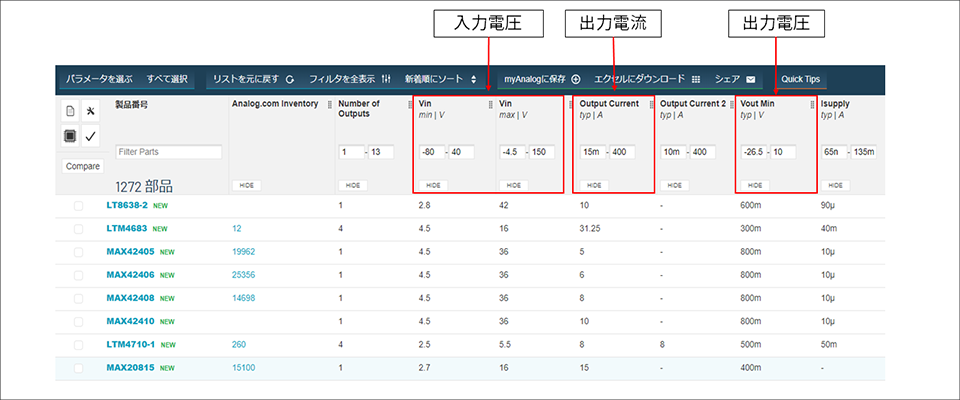
However, this is a simple investigation, so when actually proceeding with the investigation, it is necessary to read the data sheet and confirm the characteristics. In particular, when it comes to output current, the current value that can be output by the same IC varies depending on the input and output voltage values, so it is necessary to carefully monitor the output current.
Figure 2 is a graph of the LTC1877's input voltage versus output current. Datasheets often include graphs like this, so be sure to check them out.

Figure 2: LTC1877 input voltage vs. output voltage.
Point 2: Maximum duty ratio
You should also check the data sheet for voltage as well. What you need to pay attention to in this case is the duty ratio. The duty ratio of a step-down DC/DC converter can be expressed as Vout/Vin, and the maximum duty ratio is determined by the IC. It is not possible to output a voltage that exceeds the maximum duty ratio.
For example, a step-down DC/DC converter with a maximum duty cycle of 80% and an input voltage of 5V cannot output a voltage higher than 4V. In other words, even if the input/output voltage is within the specification range, it may not be possible to use it depending on the conditions, so please be careful.
Point 3: Package
It is also important to check the package when selecting an IC. Even if it meets the specifications in terms of performance, if it cannot be implemented, it cannot be used.
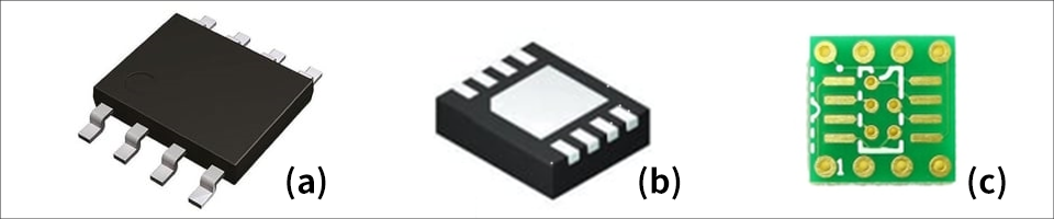
Since my purpose was to mount it on a universal board, I selected an SOP package IC with the electrodes exposed outside, and soldered it onto the DIP conversion board (like a QFN package, the electrodes are on the back of the IC). soldering is difficult for some types). In this way, when selecting an IC, it is necessary to check not only the performance, but also the type of package. Additionally, since DC/DC converters with built-in switching elements generate heat themselves, the thermal resistance value must also be taken into account.
Inductor selection
After selecting a DC/DC converter, you must also select peripheral components. For controller type ICs, the selection of FET is very important, but I chose an IC with a built-in FET, so I will omit that topic this time. If you would like to know more about FET selection, please refer to the article below.
Part 4: How to select MOS-FETs in DC/DC converter circuits (Part 1)
Among other peripheral components, I felt that it was important to select the inductor, which has a large effect on the performance of the DC/DC converter, so I will now introduce how to select the inductor. In order to select an inductor, it is necessary to calculate the required inductance value.
This time, we will introduce how to calculate the inductance value in a step-down DC/DC converter.
f sw = switching frequency
ΔI L = inductor ripple current
The required inductance value can be found using the above formula.
From this equation, we can see that a small inductor can be used if ΔIL is allowed. However, as shown in the formula below, as ΔIL increases, the ripple voltage also increases.
ESR = equivalent series resistance of the output capacitor
Therefore, in general, the required inductance value is often calculated by setting ΔIL to approximately 40% of the maximum output current, but please also check the information in the data sheet. Calculating the inductance value was very difficult, so I hope you will remember the calculation method introduced here.
Also, please note that when selecting an inductor, it is necessary to pay attention not only to the inductance value but also to the rated current of the inductor.
Summary
This time, we introduced the selection of DC/DC converters and inductors.
I'm sure there are many more points to check, but I hope what I've introduced here will be of some help. Also, in order to avoid making the same mistake as me, I would like you to make a selection with a margin.
Next time, we will finally talk about board design. looking forward to.
The path to my first circuit design Article list
・DC/DC converter selection
・ DC/DC converter board design
・ Implementation of DC/DC converter
・ Bonus