- Semiconductor BusinessHOME
- Products and Services of Macnica,Inc.
-
technical information

-
Events and Seminars
- Handling Manufacturer
- Support
- Inquiry
- Click here to purchase products
- Semiconductor business e-mail magazine registration
![]()
![]() Narrow down by specifying conditions
Narrow down by specifying conditions
現在2191件がヒットしています。check

Hello. I'm Tonpa, a new FAE.
I joined Macnica as a new graduate and learned about circuit design and implementation while experiencing manufacturing through production training. When I was a student, I majored in organic chemistry, and since I started with no knowledge of electricity and electronics, I often struggled.
Therefore, in this article, I will introduce what I learned about circuit design and implementation while experiencing manufacturing through manufacturing training. This time, we will introduce the types of DC/DC converters, which are power ICs.
What is a DC/DC converter?
Before we explain the types, what is a DC/DC converter? I'm sure some people think that, but at first I was one of them.
Simply put, it is a converter that changes the voltage from direct current (DC) to direct current (DC). The incoming voltage can be converted and output as shown in Figure 1.
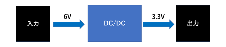
Additionally, in order to use a DC/DC converter mounted on a board, peripheral components such as FETs, inductors, diodes, capacitors, and resistors may be required.
We will introduce the selection of peripheral parts in a separate article.
Types of DC/DC converters
There are two main types of DC/DC converters: linear regulators and switching regulators.
The advantage of a linear regulator is that it has fewer peripheral components and less noise, but its disadvantage is that it has lower efficiency. On the other hand, switching regulators have the advantage of high efficiency, but the disadvantage is that they have many peripheral components and relatively high noise.
I used ICs called buck and boost type switching regulators in my production training, so I will introduce these two types of switching regulators. Generally, they are called step-down DC/DC converters and step-up DC/DC converters. The difference between the two is as the name suggests: an IC that lowers the voltage below the input voltage is a buck type, and an IC that raises it above the input voltage is a boost type.
Difference in mechanism
Even though buck and boost switching regulators are the same, their control methods differ due to their different circuit configurations.
The major difference in the circuit configuration is the location of the inductor, which is placed before the switching element in buck types and after the switching element in boost types. An inductor has the property of allowing a constant current to flow through it. If a current flows, it converts electrical energy into magnetic energy and stores energy so that the current does not flow.
On the other hand, when the current is stopped flowing, the energy stored to maintain the current is released. Switching regulators use this property to increase or decrease voltage.
I really struggled to understand the properties of inductors. . .
If you would like to know more about inductors, please refer to the article below.
Coil magic ~boosting~
Next, we will explain the operating principles of buck and boost DC/DC converters.
■Step-down DC/DC converter
The operation of a switching regulator consists of two states: when the switch is ON and OFF.
When the switch is ON, current flows into the inductor via the switch and energy is stored. In the switch OFF state, the power supply is disconnected from the circuit. At this time, the inductor releases the stored energy and supplies it to the load instead of the power source.
By repeating these two operations alternately, the input voltage can be stepped down to any desired level and output. In addition, the output voltage is smoothed by the output capacitor, so a constant voltage can be maintained.
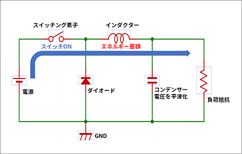
Figure 2-1: Step-down DC/DC converter circuit configuration switch ON
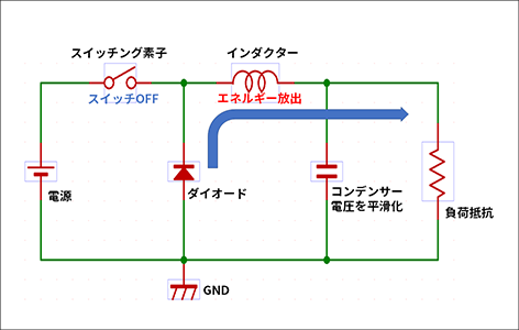
Figure 2-2: Step-down DC/DC converter circuit configuration switch OFF
■Step-up DC/DC converter
Like the buck type, the boost type operates in two states: ON and OFF.
When the switch is ON, current flows into the switch via the inductor, and energy is stored in the inductor. When the switch is off, the inductor can generate a voltage higher than the input voltage by supplying the stored energy along with the power supply to maintain the current.
As mentioned above, in the step-up type, the supply from the power supply to the inductor continues both when the switch is ON and OFF, and a higher voltage can be generated when the switch is OFF, so the input voltage is boosted to the desired level and output. can do.
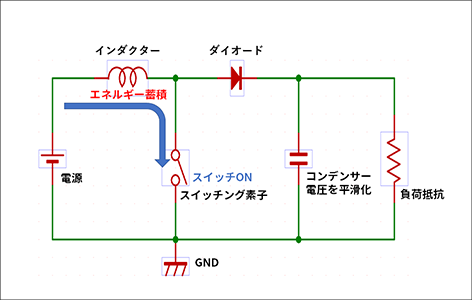
Figure 3-1: Circuit configuration of step-up DC/DC converter when switch is ON
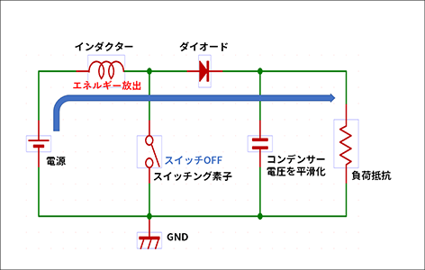
Figure 3-2: Circuit configuration of step-up DC/DC converter when switch is OFF
In this way, even the same switch regulator operates differently depending on the circuit configuration (especially the position of the inductor and switch).
Additionally, switching regulators include buck-boost ICs that can perform both step-down and step-up operations, and inverting ICs that can output negative voltage. However, since it was not used in the production training, it will be omitted from this article.
If you would like to learn more about switching regulators, please refer to the article below.
How to use step-up/step-down DC/DC regulators (*Links to Analog Devices page.)
Summary
In this article, we introduced the types of DC/DC converters.
To summarize, a DC/DC converter is a transformer that changes the voltage from direct current to direct current, and can be divided into two types: linear regulators and switching regulators. Additionally, switching regulators include buck types that lower the voltage, and boost types that increase the voltage, and the inductor plays an important role in the difference in operation.
Next time, we will introduce the selection of DC/DC converters and peripheral components.
The path to my first circuit design Article list
・ DC/DC converter board design
・ Implementation of DC/DC converter
・ Bonus