- Semiconductor BusinessHOME
- Products and Services of Macnica,Inc.
-
technical information

-
Events and Seminars
- Handling Manufacturer
- Support
- Inquiry
- Click here to purchase products
- Semiconductor business e-mail magazine registration
![]()
![]() Narrow down by specifying conditions
Narrow down by specifying conditions
現在2136件がヒットしています。check

Introduction
This article is a Japanese translation of a blog post published on the Skyworks website.
There are many technical articles about clocks, and this second one touches on the "differences in structure between Analog PLL (APLL) and Digital PLL (DPLL)".
If you're interested, be sure to read the original Skyworks blog post.
Skyworks Technical Blog Article "Timing Timing 201 #7: The Case of the Dueling PLLs - Part 1"
*For the first article, "How to calculate total jitter when connecting multiple clock ICs?", please click here.
Conventional PLL configuration and Skyworks' DSPLL technology
RF and microwave frequency synthesizers often employ multiple series-connected (cascaded) Analog PLLs (APLLs).
This structure offers a trade-off between improved phase noise, smaller frequency step size, and faster switching, and increased complexity.
There are various purposes for connecting and using multiple PLLs, such as
・PLL1: Each PLL is used to generate any output frequency from a different reference frequency.
-PLL2: Ensures a smooth synchronization loop when switching between multiple reference signals.
・PLL3: Removes jitter contained in the external clock signal to generate a clean clock.
Other: Achieving low phase noise
By using a specific PLL with low noise design and using the output of another PLL as the reference signal, the phase noise of the entire system is reduced.
Another example is isolating phase noise between PLLs to minimize noise in specific operating frequency bands.
Skyworks uses a cascaded Analog PLL (APLL) as opposed to a serially connected Analog PLL.
They use a PLL that incorporates their unique technology, a DSPLL with a dual loop structure that consolidates all the signals into a single PLL.
In the white paper "Optimizing Clock Synthesis in Small Cells and Heterogeneous Networks,"
This article explains the DSPLL used in the jitter cleaner (Si538x) for small cell applications.
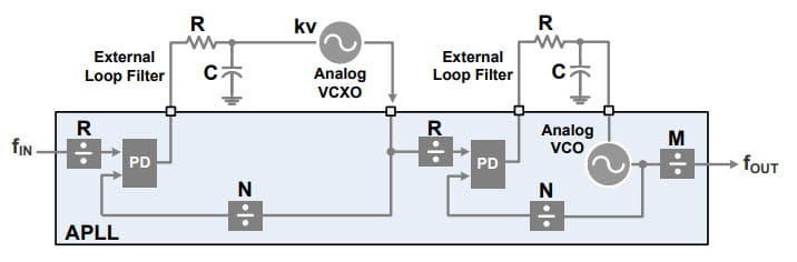
Series-connected Analog PLL (APLL)
The diagram below shows a cascaded Analog PLL (APLL).
The term cascade here means connecting two PLLs together or in series.
By connecting two PLLs in series, a combined jitter removal and frequency synthesis system can be realized.
The PLLs on the left and right sides of the diagram are referred to as PLL1 (left) and PLL2 (right), respectively.
・PLL1
-Uses VCXO (analog voltage controlled oscillator).
- Functions as a narrowband jitter attenuator.
- Attenuates output clock jitter and passes a clean clock signal to PLL2.
・PLL2
- Functions as a wideband clock generator.
- Receives the output clock of PLL1 and generates the desired output clock frequency.
Because the PLL design shown in the figure requires an external analog voltage-controlled oscillator (VCXO) and loop filter, it is classified as an Analog PLL (APLL).
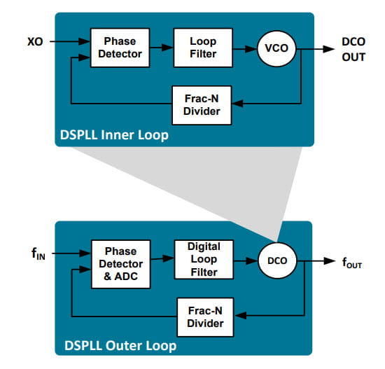
Dual-loop Digital PLL (DSPLL)
The diagram below shows a Digital PLL (DSPLL) with a dual loop structure integrated into a single PLL.
It has a double loop structure that combines two PLLs: an inner loop (IL) and an outer loop (OL).
・Outer Loop (OL)
- Includes digital loop filter.
- Role of controlling the operation of the inner loop (IL).
・Inner Loop (IL)
- Functions as a VCO (voltage controlled oscillator) for the outer loop.
・In practice, a DCO (digitally controlled oscillator) is used instead of a VCO.
In this way, one loop is placed inside another, creating a double loop structure.
How it works is that the output of the digital loop filter in the outer loop (OL) modulates (adjusts) the return path of the inner loop (IL).
In other words, the operation of the inner loop (IL) is controlled by the outer loop (OL).
Finally, the clock signal (fout) is output from the VCO (DCO) of the inner loop (IL).
*In an actual system, this fout is further divided to generate the required output clock.
The inner loop (IL) and outer loop (OL) are tuned to allow optimization of phase noise performance.
In this way, Digital PLLs (DSPLLs) with a dual-loop structure consolidated into a single PLL are used for more accurate frequency synthesis and low phase noise designs.
The loop filter and part of the VCO are made up of digital circuits and have programmable characteristics, so it is classified as a Digital PLL (DPLL).
Challenges of APLL and Advantages of DSPLL
The challenges of serially connected Analog PLLs (APLLs) are:
Since the VCXO is external to the IC, it requires an external control voltage and must have good close-in phase noise (noise with low frequency offsets).
The internal VCO must operate at a sufficiently high frequency and have low phase noise even at high offset frequencies.
As such, high-performance VCXOs, filters, and other external elements are required, and issues arise such as component selection, constant determination, increased cost for the external components, and increased area.
The advantages of the dual loop Digital PLL (DSPLL) are:
No external VCXO or loop filter is required; these are nested internally and optimized by digital control.
Fewer components leads to lower costs, a smaller mounting area, and reduced design man-hours.
DSPLL Considerations
In a Digital PLL (DSPLL) feedback control loop, which has a dual loop structure, the inner loop must be faster than the outer loop.
If the loop speeds were equal, the loops could interfere with each other and cause stability problems.
Combining a fast PLL with a slow DCO will result in a delay in the loop because the PLL will respond too fast for the DCO to keep up.
Combining a slow PLL with a fast DCO is less likely to cause problems because the response of the PLL is slow, so the fast DCO does not have a significant impact.
For this reason, it is desirable to design the inner loop to be wideband (fast) and the outer loop to be narrowband (slow).
Also, to stabilize the system, the inner loop should be locked first.
The outer loop operates under the assumption that the inner loop is locked, so if the order is reversed, it will be unstable.
Summary
The series-connected Analog PLL (APLL) is a conventional configuration, but it is significantly affected by external components such as the VCXO and loop filter circuit.
On the other hand, Digital PLL (DSPLL), which has a dual loop structure, has similar element functions built into the PLL, so it offers greater design freedom compared to the general Analog PLL (APLL) structure, and offers advantages in terms of BOM cost and implementation area.
Skyworks' clock ICs use their proprietary DSPLL technology to achieve low jitter and high precision clock generation.
Related article
If you are interested in Skyworks' low-jitter clock ICs with DSPLL, please read the article below.
[DL available] SKYWORKS timing products and complete lineup information
To Skyworks manufacturer information Top
If you would like to return to the Skyworks manufacturer information top page, please click below.