- Semiconductor BusinessHOME
- Products and Services of Macnica,Inc.
-
technical information

-
Events and Seminars
- Handling Manufacturer
- Support
- Inquiry
- Click here to purchase products
- Semiconductor business e-mail magazine registration
![]()
![]() Narrow down by specifying conditions
Narrow down by specifying conditions
現在2182件がヒットしています。check

Introduction: A review of how it works
I'm Kuro-chan, a new engineer on Infineon's automotive team!
Until last time, we have focused on the hardware design with the main unit in mind, but this time we will focus on the software design with the controller in mind.
But first, as a refresher, I'd like to explain how this device is designed to move around.
First of all, the main body can move in eight directions using three tires called omniwheels, which can also move vertically.
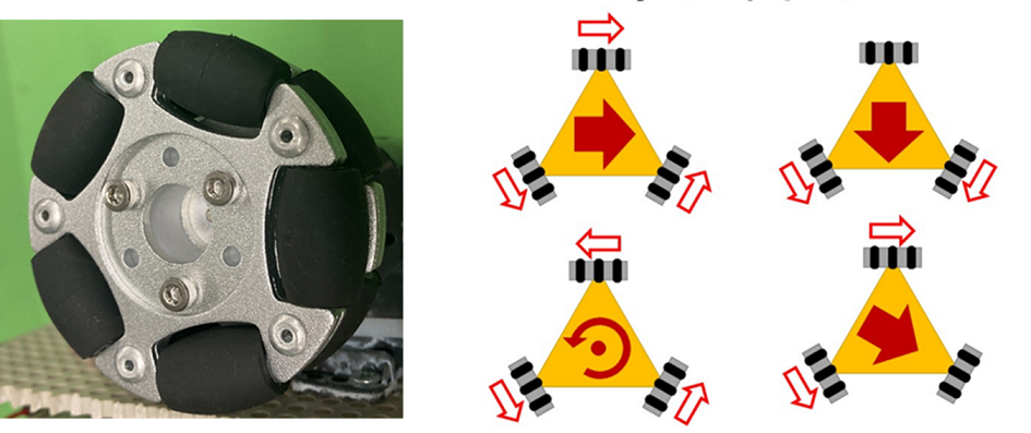
Omniwheel (left) Three-wheel drive (right)
For operation, a 3D Magnetic Sensor made by Infineon is used to implement a joystick like a game console controller to control the movement of the main unit.
In addition, by implementing three new buttons, a right rotation, left rotation, and a stop button have been added, allowing a total of 11 movement controls to be performed from the controller. The appearance of the controller is now as follows!
Next, we will explain what kind of control will be implemented using the actual controller.
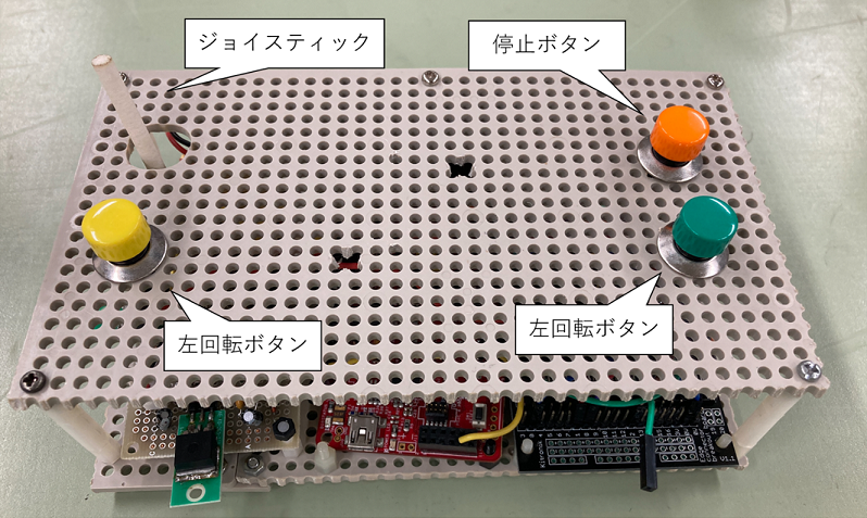
Controller appearance
Controller specifications: Designing is really hard work
There are 11 operations that the controller can control, so for each condition, four I/O pins are used to send signals to the main unit. In addition, to determine whether the actual signal matches the operation when a signal is sent, turn signals are attached to the four corners of the main unit and the turn signals light up in response to each operation. The feedback for each input port is as shown in the table below.
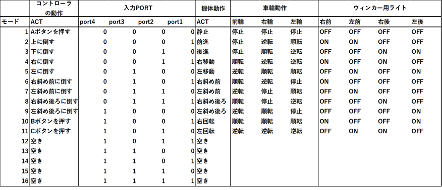
Controller input and movement control
The following is a simple flowchart showing how the controller was controlled.
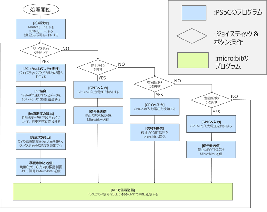
Controller flow chart
The interface between this 3D sensor and the microcontroller uses I2C, with the microcontroller acting as the Master and the 3D sensor acting as the Slave to exchange various signals.
First, when you turn on the controller, the microcontroller will send a Write I2C command to the 3D sensor to change the initial settings.
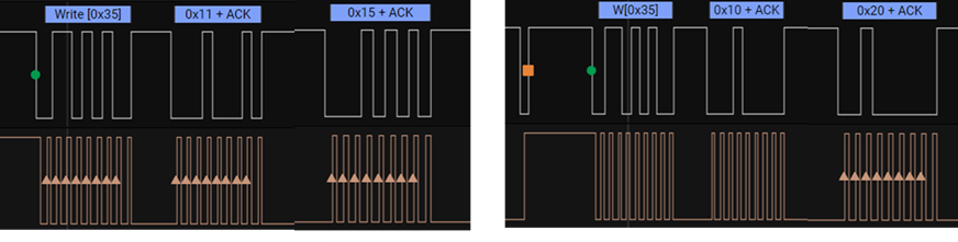
I2C Master-Write Waveform
Next, by moving the joystick, the microcontroller receives an I2C read from the 3D sensor regarding the magnetic flux density on three axes due to the tilt of the joystick, and calculates the joystick angle θ using the X-axis and Y-axis data from the magnetic flux density information on the three axes.
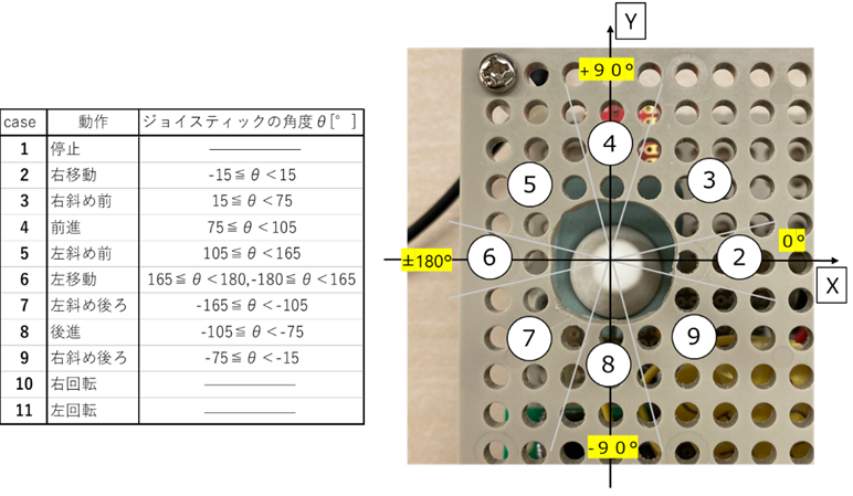
Joystick and angle detection
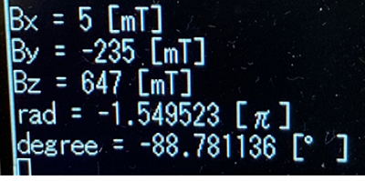
When reading from the microcontroller to the 3D sensor, the UART is used for debugging purposes to enable the magnetic flux density of the three axes and the joystick angle θ corresponding to the magnetic flux density to be viewed.
I2C Master-Write Waveform
Then, a movement control signal determined by the calculated angle θ is sent to the housing via wireless communication to control the main body.
This is one set, and it controls the movement of the main body. Mechanical switches are used for stopping, right rotation, and left rotation, and they are programmed to take priority regardless of the state of the previous flow chart.
That's the whole process, but Kuro-chan, who is a programming beginner, had a lot of trouble with the software.
Software design: I hyperventilated due to stress.
If someone asked me, "What do you think is the most difficult part of programming?" I would answer without hesitation, "Debugging!!"
There were times when the whole day ended without any progress. I was so stressed that no matter how much I debugged, nothing improved, and I nearly collapsed from hyperventilation. Without a doubt, the most stressful part of this production training was the software design.
The most difficult part was programming and debugging the I2C. I was particularly struggling with not being able to send the 3D sensor Write signal, and debugging this was extremely difficult.
The MCU used here is a microcontroller from the PSoC™ series manufactured by Infineon, which allows you to customize the analog and digital circuits by freely selecting and configuring them.
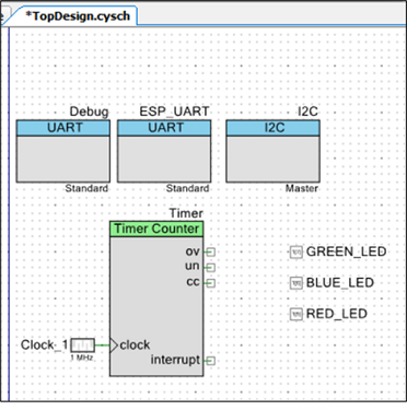
PSoC ™ Component Examples
I used this I2C component to communicate with the 3D sensor, but I encountered a problem here as well.
I thought I would just need to use I2C to send the output of the 3D sensor to the microcontroller, but the communication isn't working properly.
I was looking at the PSoC™ datasheet and user manual again to debug, but isn't there too much text?
After staring at the documentation for a day, I discovered that the PSoC™ was set to receive 1 byte of data by default, while the 3D sensor was set to send 2 bytes of data by default. So, I changed the 3D sensor settings to send 1 byte, and finally I was able to receive I2C data!!
Although the workshop was full of ups and downs, including various other incidents, they managed to complete the soccer robot! (I would love to share that story in a bonus page.)
Kuro-chan's rookie blog has been a hectic one, but the next episode will be the final one.
Next time, I will finally have a match between my robot and a commercially available soccer robot, so please stay with me until the end!
[A rookie engineer's soccer robot production diary]
Episode 1: "Macnica Cup is being held?!"
Episode 2 “Is this the strongest soccer robot? ! Your name is Maradona! ! ”
Episode 3: "Maradona, the Phoenix who comes back to life even after being burned"
Episode 4: "The time to wake up has come, let's go! Maradona-kun!!"
Episode 5 "KICK OFF of Fate! ! The one who will take the crown is...