- Semiconductor BusinessHOME
- Products and Services of Macnica,Inc.
-
technical information

-
Events and Seminars
- Handling Manufacturer
- Support
- Inquiry
- Click here to purchase products
- Semiconductor business e-mail magazine registration
![]()
![]() Narrow down by specifying conditions
Narrow down by specifying conditions
現在2149件がヒットしています。check

Click here for the previous article: Episode 2 Is this the strongest soccer robot? ! Your name is Maradona! !
Introduction ~First errand in Akihabara~
Up until the last time, everything from the concept to the specifications had been decided smoothly, so I would like to start the hardware design right away.
By the way, I went to Akihabara, which is famous for its electric town, to purchase each part! I was excited to be visiting a specialty store that sells electronic parts for the first time, but I was surprised at how many electronic parts there were.
I'm not used to it, so it took me over 5 hours to get all the parts together (hohoho...)
Now, if I had the chance, I would like to write all about how I designed the hardware, but since I couldn't fit it into one page, I had a particularly hard time designing the hardware this time (in many ways). I'll cut out the scene and tell you about it!
Implementation of the power supply section ~Fire Nemomakezu~
First, let's talk about the implementation of the power supply section, which is the heart of the robot and causes a certain big incident.
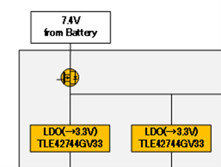
The power supply section mainly incorporates a reverse connection protection circuit and an LDO. This way, you don't have to worry about accidentally connecting the battery the wrong way! (Absolutely not!!)
I used a breadboard to conduct an evaluation in which a current flows in the opposite direction, assuming a reverse connection, but there were no problems.
Next, I created a pseudo-circuit on a breadboard for an LDO that steps down to 3.3V to supply power from the power supply to each control IC, and evaluated it, and it worked without any problems.
The evaluation has progressed smoothly, so next time I would like to finally start mounting the board!
Kuro-chan, who was progressing smoothly so far, must have let his guard down somewhere, and finally causes an incident.
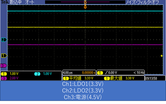
Board mounting was progressing smoothly, and we were now at the stage where we could evaluate the board. When I was connecting it to a stabilized power supply and using an oscilloscope to evaluate whether a proper 3.3V was being applied to the output from the LDO, I noticed a burning smell, and the next moment I connected it to the board. The lead wire burst into flames!
I was so shocked that all I could do was stand there dumbfounded, and it was only after the lead wires were reduced to ashes that I was able to understand what was happening and grasp the situation.
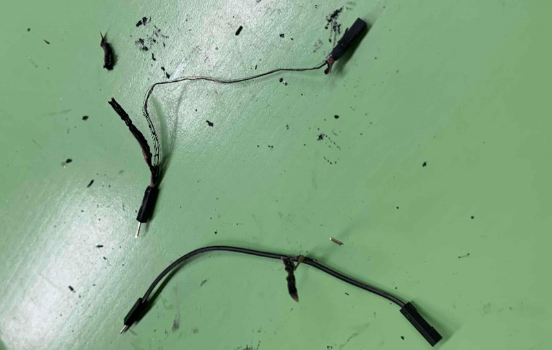
The reason this lead wire caught fire was because when I was mounting it on the board, I soldered it in the wrong circuit configuration, causing a short circuit between the power supply and GND.
After this fire, I started properly checking continuity using a tester (slow!)
There were many twists and turns, but we managed to finish mounting the source supply section on the board!
Next, we will move on to the evaluation and implementation of the drive section, which was very difficult to implement.
Implementation of the drive unit - Too hard hardware design -
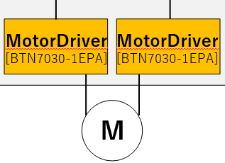
Now, regarding the drive part, this time we will drive the DC motor with H Bridge.
To do this, we will use an Infineon IC that integrates two gate drivers and MOS to control the motor.
However, there was one major problem when implementing this IC.
VSWhere is the terminal? !
The heat dissipation pad at the bottom of the package for this IC is VS.
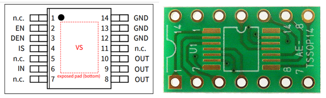
The printed circuit board I bought does not have the heat dissipation pad connected to the pins, so I have to somehow process the VS part and create a path that connects the NC pin to VS.
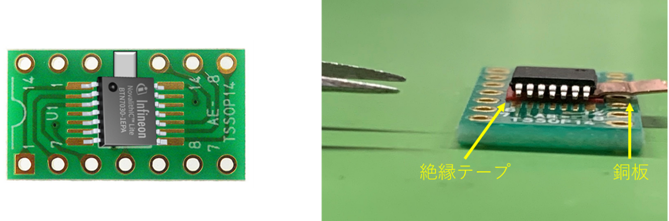
To do this, attach a copper plate to the VS pad and connect the output to the VS terminal to pin 11, which would normally be NC.
Furthermore, we had to perform extremely time-consuming work such as attaching vinyl tape to insulate the holes in the printed circuit board to prevent them from accidentally connecting with the VS pads.
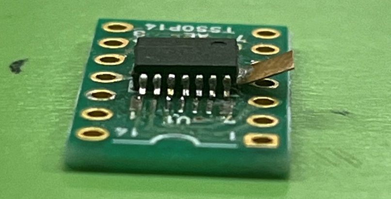
This task was extremely difficult. . As you can see in the photo, the legs of the IC are floating, creating a distance to the pads on the printed circuit board, and even if you try to solder normally, it won't stick well. It will stick.
After a lot of hesitation, as a last resort I managed to connect the pad to the leg by slightly breaking the leg of the IC!
This motor driver was the most difficult part of the hardware implementation for this robot, but there were still issues to be solved.
It was about evaluation using a motor after attaching it to a PCB board.
It is necessary to use two ICs in an H-bridge configuration to control forward and reverse rotation of the motor. In this evaluation, we will evaluate whether forward and reverse rotation of the motor actually works.
First of all, it was a simple forward and reverse control using a stabilized power supply, and I was able to operate it without any problems.
However, the next time I tried to perform forward and reverse rotation control using simple programming, a problem arose again.
The problem was that switching from forward rotation to reverse rotation and from reverse rotation to forward rotation did not go well, and no matter how many times I tested it, for some reason the motor would stop at the timing of switching between forward rotation and reverse rotation.
I performed various verifications, but I couldn't quite figure out the cause, and I was at a loss, but when I went back to the basics and looked over the data sheet to see if I had missed something, I finally found a description that seemed to be the cause. I was able to find a sentence!
"To avoid strain on the device, we recommend freewheeling until the load current reaches 0."
Hmmm, I see.
Generally, when controlling forward and reverse rotation of a motor, a freewheel diode is often used to control back electromotive force.
This time, instead of using a freewheel diode, I decided to implement programming that allows time for both low side MOSFETs to be turned on, so that the current flowing from the load flows to GND.
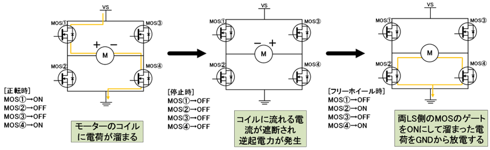
We were then able to control the motor once again using programming that included a freewheel, and we were finally able to complete a stage in the hardware design.
Next time I'll finally get started on software design, so stay tuned!
[A rookie engineer's soccer robot production diary]
Episode 1: “Macnica Cup is being held?!”
Episode 2: “Is this the strongest soccer robot? ! Your name is Maradona! !”
Episode 3: “Come back to life as many times as you like!” Phoenix Maradona! ! ”
Episode 4 "The time has come to wake up, let's go! Maradona-kun!!"
Episode 5 “Fateful KICK OFF! ! The person who will take that crown is...''