- Semiconductor BusinessHOME
- Products and Services of Macnica,Inc.
-
technical information

-
Events and Seminars
- Handling Manufacturer
- Support
- Inquiry
- Click here to purchase products
- Semiconductor business e-mail magazine registration
![]()
![]() Narrow down by specifying conditions
Narrow down by specifying conditions
現在2191件がヒットしています。check


I'm Taro. This time, I will write about division/multiplication by PLL (Phase Locked Loop).
As I introduced in the previous rookie engineer's blushing blog "About buffers", the main components of the PLL were PFD / CP , LPF , and VCO.
The PLL functions as a frequency divider/multiplier by adding a divider to the reference signal (hereafter REF)/feedback signal (hereafter FB).
This time, I will write about the principle.
Division by PLL
The PLL frequency divider circuit has a frequency divider attached to REF as shown below.
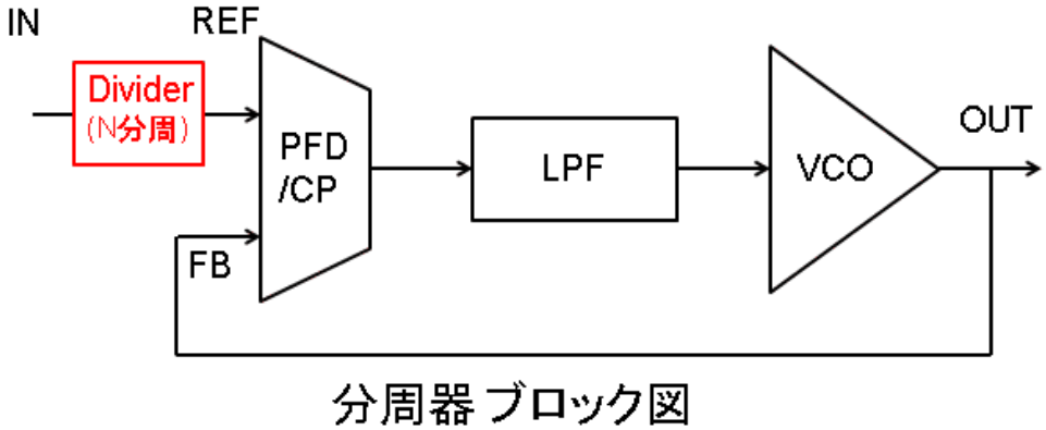
As an example, if the input (IN) is 100 MHz and the divider divides by 4, REF will be 1/4 of IN, 25 MHz.
The PFD/CP then adjusts the phase/frequency of FB to match the phase/frequency of REF.
The PFD compares the phase/frequency of REF and FB and continues to output UP/DOWN signals until the phase/frequency of REF and FB are equal.
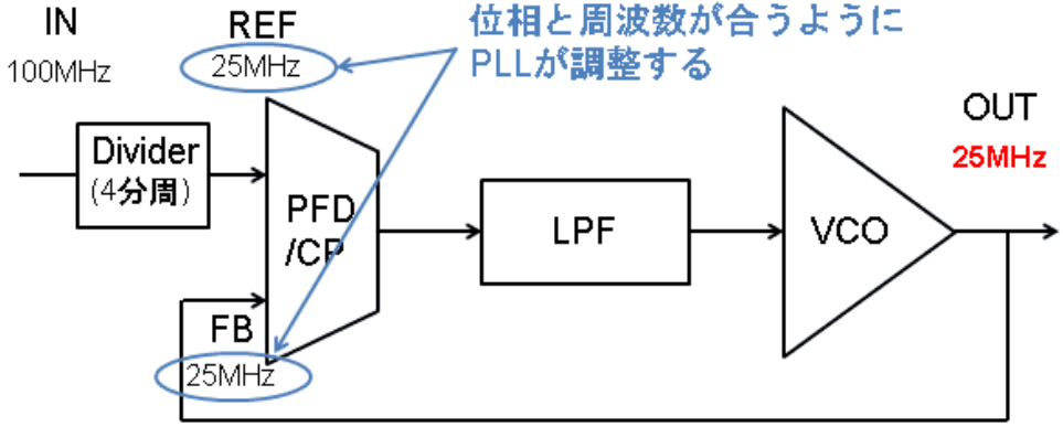
This is how the division by the PLL is done.
However, looking at this block diagram, there may be people who think that frequency division can be achieved only with a frequency divider, without going through the trouble of going through the PLL.
If it is only for the purpose of "division", it is certainly possible to achieve it with only a frequency divider.
However, if you want to synchronize between the input and output, you need a PLL.
In addition, division by the PLL regenerates the clock signal with the VCO for the input signal, so the accuracy of the signal depends on the VCO.
A PLL using a VCXO (Voltage Controlled Crystal Oscillator) can provide a more accurate signal than the input signal.
Also, there may be a divider after OUT as well as before REF.
Combining the frequency divider before REF and the frequency divider after OUT enables more flexible frequency output.
Multiplication by PLL
"Multiplication" means to multiply the input frequency by n times. At first, the kanji was difficult and I was a little scared (laughs).
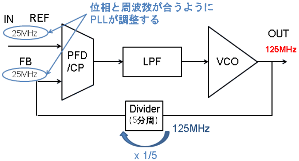
The multiplier circuit of PLL has a divider in FB as shown in the figure below.
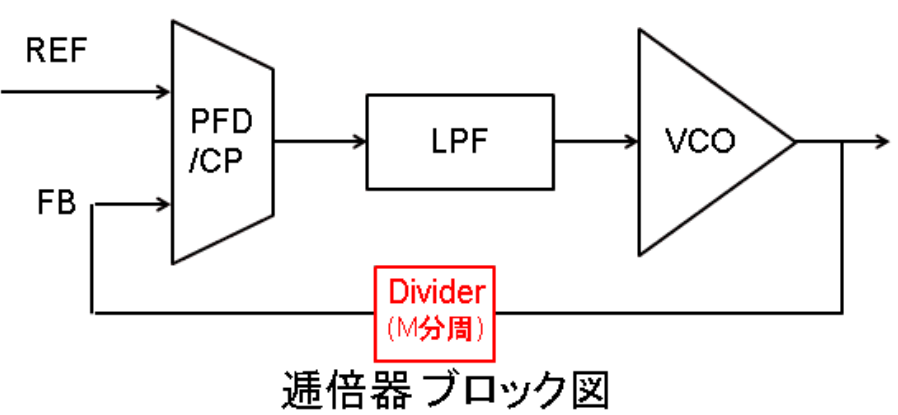
As an example, if the input (IN) is 25 MHz and the divider divides by 5, the output will be 5 times 125 MHz in order to match FB to 25 MHz.
This is how the frequency multiplication is done in the PLL.
Combined Divide/Multiply PLL
Combining frequency division/multiplication by the PLL allows you to create frequencies more freely.
For example, if the REF divider divides by N and the FB divider divides by M, the output frequency will be M/N times the input frequency.
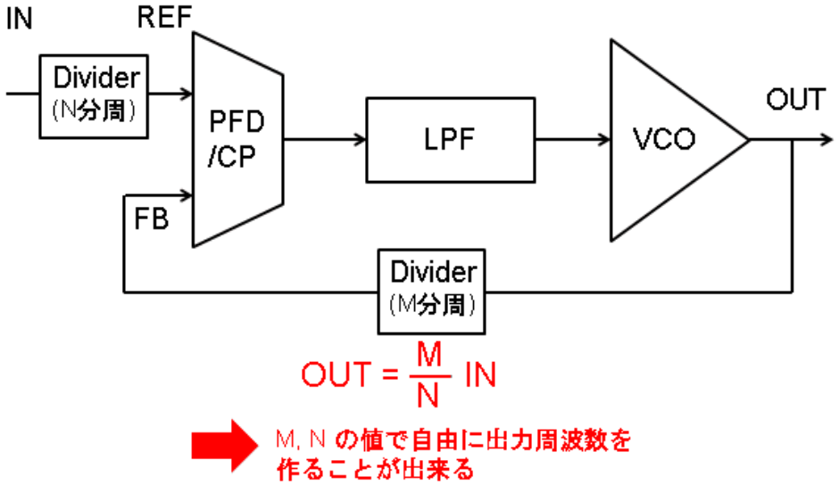
As you can see from the above figure, the degree of freedom of the M and N values of the frequency divider is directly linked to the degree of freedom of the frequency to be generated.
IDT 's products are divided into Integer PLL built-in type and Franctional PLL built-in type, but "Integer" and "Franctional" here indicate the resolution of M and N in the above figure. .
FemtoClock® NG, a product of IDT, can use FB division depending on the signal that inputs Integer / Fractional to the pin.
FemtoClock® NG is characterized by very low phase Jitter. By using the Fractional FB, the frequency resolution is increased and the frequency can be set in steps of several tens of Hz. Output phase Jitter is 0.5 ps rms.
On the other hand, Integer FB has lower resolution than Franctional FB, but the output phase Jitter is 0.2 ps rms and can output extremely accurate frequency. Whether to use Integer / Franctional depends on the user's specifications, but in any case the jitter of the output signal is small!
Clock generators and synthesizers use this PLL principle to create the desired frequency.
Next time, I will write about how to apply PLL.