- Semiconductor BusinessHOME
- Products and Services of Macnica,Inc.
-
technical information

-
Events and Seminars
- Handling Manufacturer
- Support
- Inquiry
- Click here to purchase products
- Semiconductor business e-mail magazine registration
![]()
![]() Narrow down by specifying conditions
Narrow down by specifying conditions
現在2189件がヒットしています。check

This series uses reference circuits for evaluation boards for converter ICs to explain important characteristics in selecting various discrete components.
When explaining, use LTspice for individual characteristics, change the constants of the parts or the parts themselves, check the changes on the circuit with simulation waveforms and calculated values, and explain the relationship between the characteristics and the circuit. increase.
This time, I will explain how to select the inductor required for a synchronous rectification type buck converter circuit, and how to select the inductor characteristics, using LTspice simulations to confirm the effect of inductor characteristics. .
In the first part, we explained "the role of inductors in power supply circuits" and "inductance value: L". In this second part, we will explain "Rated current: Isat, Itemp," "DC resistance: Rdc," "Self-resonant frequency: SRF," and "Types of inductors."
Also, please refer to the following for LTspice and evaluation kits used in the explanation.
[How to download / use LTspice]
・ LTspice download page (link to Analog Devices website)
*If you want to know how to use LTspice, please check the Company article below.
[Evaluation board used/mounted regulator/board purchase information]
LT8609A Synchronous Buck Regulator - Evaluation Board: DC2958A (link to Analog Devices website)
Evaluation board DC2958A is available at Macnica-Mouser.jp. (Link to Macnica-Mouser.jp)
(Note)
This article does not describe how to select peripheral components (inductors) for the above converter IC LT8609A. It is used as a sample circuit example to check the characteristics of the inductor on LTspice.
table of contents
・Role of inductors in power supply circuits
・Inductance value: L
Part 2
・ Rated current: Isat, Itemp
・ DC resistance: Rdc
・ Self-resonant frequency: SRF
・ Inductor type
1. Rated current: Isat, Itemp
There are two main types of rated current for inductors. One is the "rated current determined by the decrease in the inductance value L (hereafter L value)" and the other is the "rated current determined by the temperature rise".
Generally, the former is called "DC superposition rated current (Isat)" and the latter is called "Temperature rise rated current (Itemp)".
(1)Isat
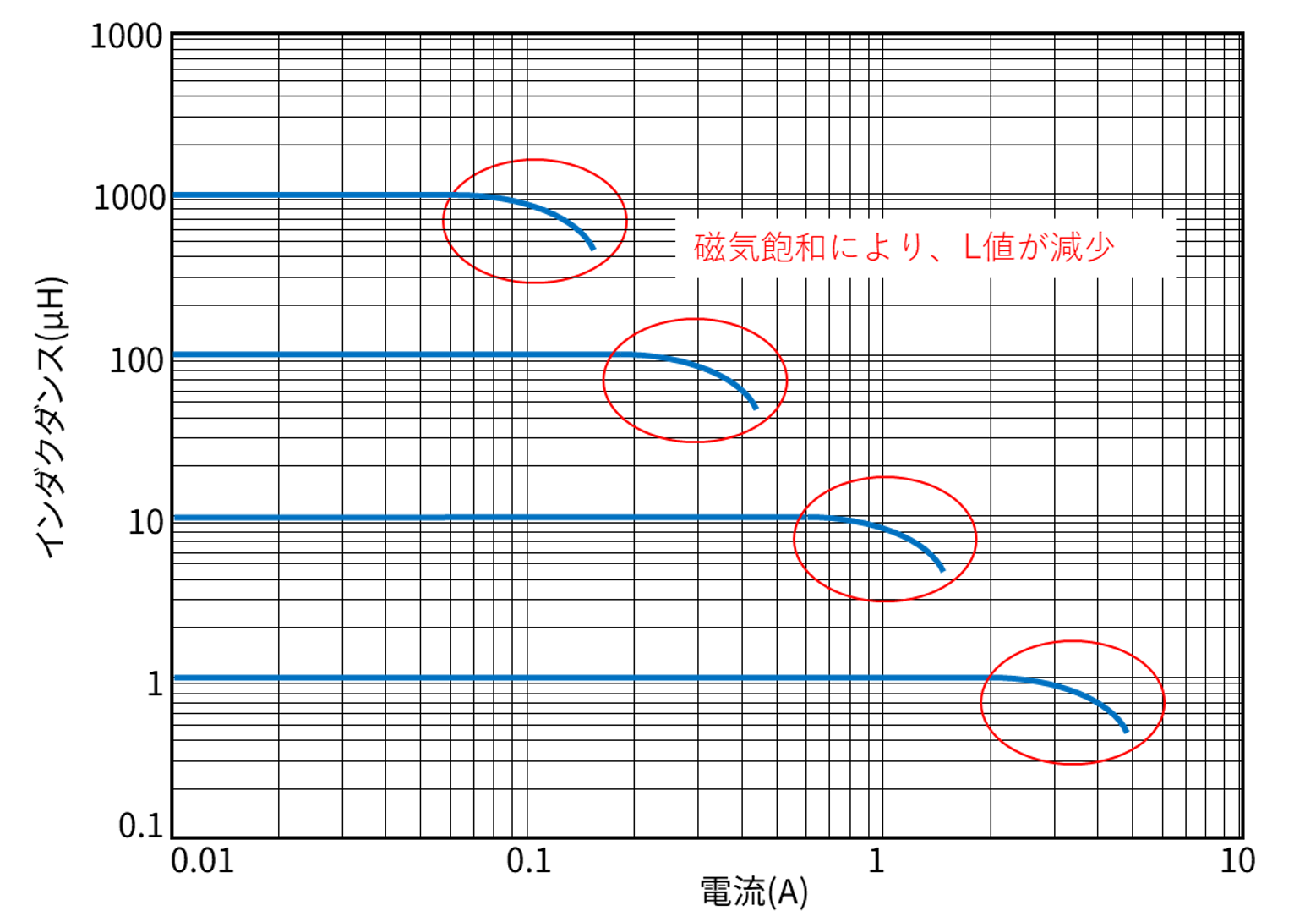
As the current flowing through the inductor increases, the L value decreases due to magnetic saturation. The current value at which the L value drops to a certain level is defined as the rated current. This is Isat. Isat refers to the current value at which the L value drops to 20% to 30%. (Specific values vary depending on the manufacturer and type of inductor, so please check the data sheet of each inductor.)
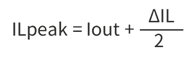
Isat must be greater than or equal to the maximum current (inductor peak current: ILpeak hereafter).
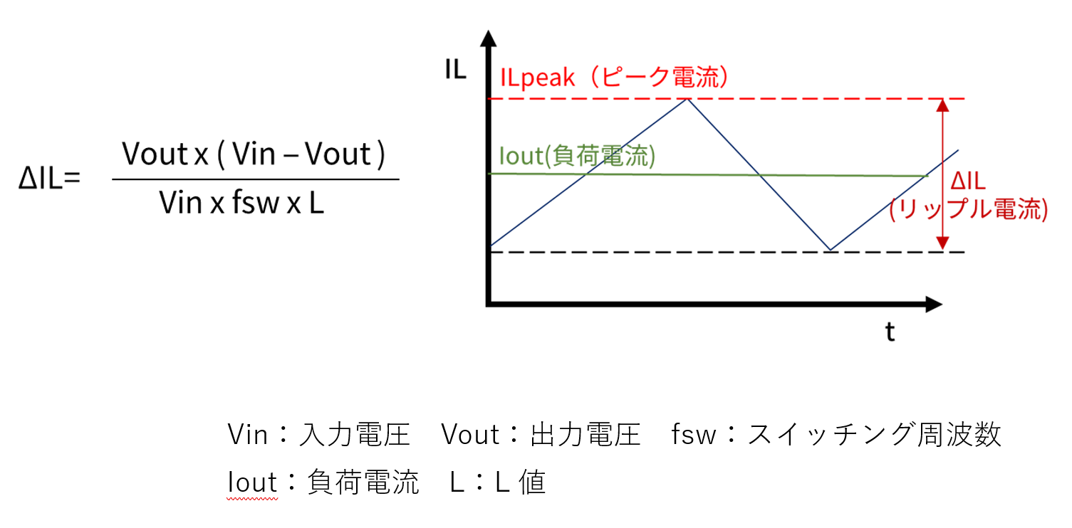
The maximum current ILpeak is the value obtained by adding 1/2 of the ripple current (ΔIL) to the load current (hereinafter Iout). ILpeak can be calculated from the following formula.
Ripple current (ΔIL) is expressed by the following equation.
If there is no margin in the rated current and the current in the load increases, the following chain will occur:
Current increase → Magnetic saturation → L value decrease → Peak current further increases
In this case, the overcurrent protection function (*) of the power supply IC operates, causing problems such as a drop in the output voltage Vout.
(Note)
- At high temperatures, saturation begins with a small current value.
- Even if the Isat is exceeded, the inductor will not be damaged, but the ripple current (ΔIL) will increase due to the drop in the L value. As a result, the operation of the power supply IC may become unstable, or the rated current of elements other than the inductor may be exceeded.
(*) The overcurrent protection function is a function that stops the output of the power supply IC when the output current becomes abnormally large due to some accident such as an output short circuit. The method of detecting overcurrent and the method of stopping the output differ depending on the product, but the overcurrent protection function of the power supply IC this time is called the frequency foldback type, which lowers the oscillation frequency and reduces the ON duty. This method limits the output current by
(2)Itemp
When current flows through an inductor, it heats up due to the resistance of the windings. The rated current value based on the self-temperature rise is specified as Itemp.
In some cases, parts may fail or be damaged if used beyond this specified value.
Itemp is defined by the current value at which the temperature rise is ⊿40°C. (Specific values vary depending on the manufacturer and type of inductor, so please check the data sheet of each inductor.)
Select the value of Itemp based on Iout or more as a guideline.
(3) Simulation
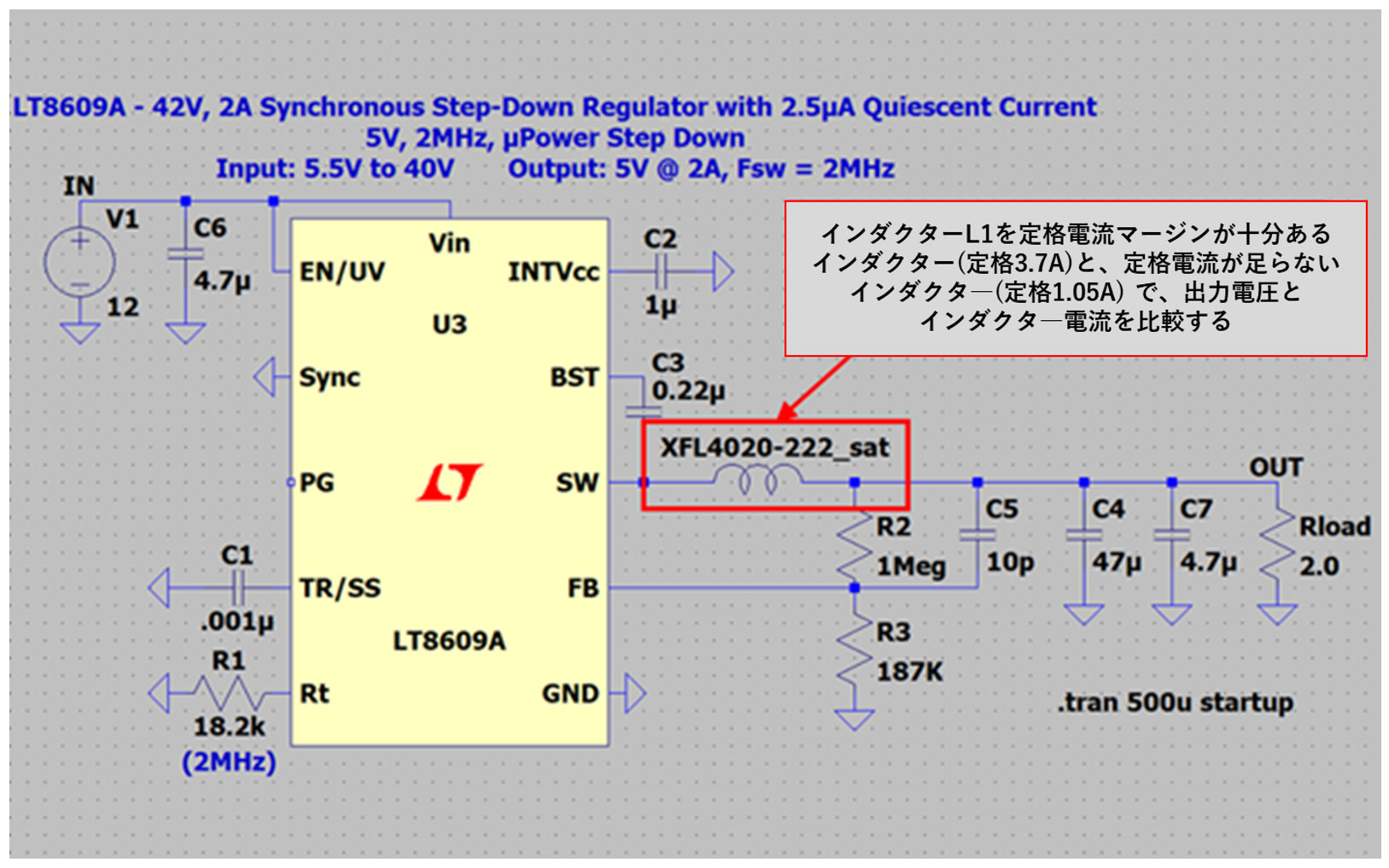
In the simulation, let's compare inductor L1 with a high rated current of 3.7A (HFL4020-222) and a low rated current of 1.05A (EPL2010-222) for a load current of 2.5A. The circuit to be simulated is shown in Figure 1.
Here, instead of a normal inductor model (static model), we use a saturation model that allows us to check the saturation state through simulation, and check the state of the inductor current when the rated current is exceeded. The saturation model is available from CoileCraft 's website at:
https://www.coilcraft.com/ja-jp/models/howto/model-libraries-for-ltspice/
(a) Simulation results for an inductor with sufficient rated current margin
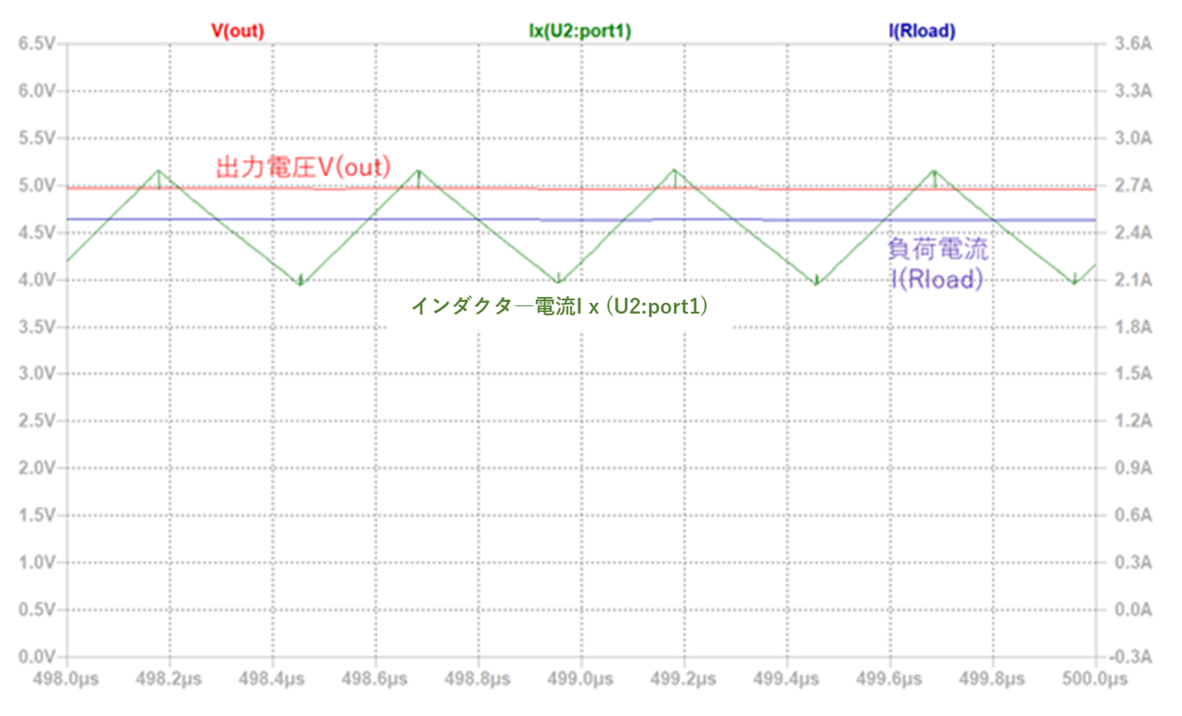
Even at a load current of 2.5A, the inductor does not saturate and the inductor current and output voltage are stable.
(b) Simulation results for an inductor with insufficient rated current margin
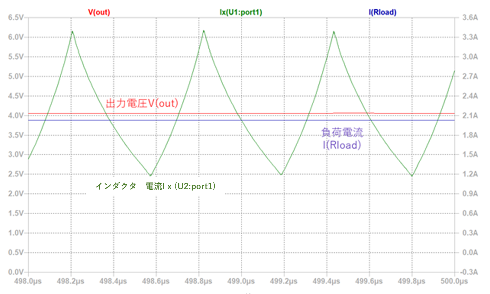
When the load current is 2.5A, magnetic saturation occurs and the inductance value decreases, resulting in a further current increase. And you can confirm that the overcurrent protection function of the power supply IC has been activated and the output voltage has decreased.
"point"
- Inductor rated currents include "DC superimposition rated current (Isat)" and "Temperature rise rated current (Itemp)".
- Isat is the current value at which the L value drops by 20% to 30%.
- Select Isat that is greater than the maximum current (inductor peak current).
- When the temperature rises, saturation starts with a small current value.
- Itemp is the current value at which the temperature rise is ⊿40℃.
- The value of Itemp should be selected so that it is greater than or equal to the load current Iout.
- If there is no margin for the rated current and the load current increases, the overcurrent protection function of the power supply IC will activate, causing problems such as a drop in the output voltage.
2. DC resistance: Rdc
Ideally, an inductor should have no components other than inductance and no energy loss. However, an actual inductor has a resistance component (DC resistance Rdc) in addition to inductance.
The smaller the DC resistance Rdc (hereafter Rdc), the less power loss due to heat generation.
If Rdc is large, power loss will increase and efficiency will drop. In addition, heat generation may adversely affect peripheral components. On the other hand, reducing Rdc has a trade-off relationship with DC superimposition characteristics and size reduction. Therefore, from among the inductors that satisfy the required characteristics such as L value and rated current (Isat, Itemp), select one with as small Rdc as possible.
In the simulation, change the Rdc of the inductor and check the efficiency status in the Efficiency Report. The circuit to be simulated is shown in Figure 2. Inductor L1 Series Resistance[Ω] Compare the efficiency when default 20mΩ and 100mΩ.
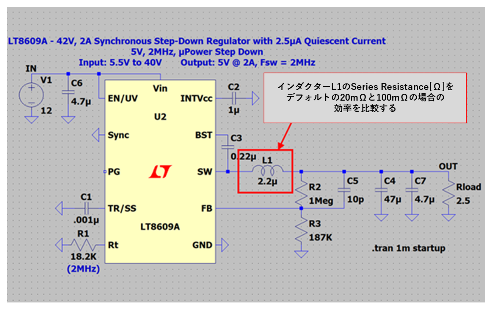
The simulation results are as follows.
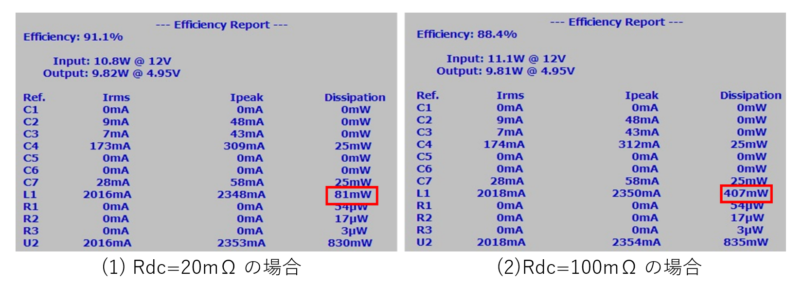
Focusing on the power value of L1 in the Efficiency Report, it is 81mW when Rdc is 20mΩ, and 407mW when Rdc is 100mΩ. It is clearly larger when Rdc is 100mΩ. This means that the power loss is higher when Rdc is 100mΩ.
"point"
- A smaller Rdc can reduce power loss due to heat generation.
- There is a trade-off relationship between the reduction of Rdc, the DC superimposition characteristics, and the miniaturization of the size.
- Select an inductor with a smaller Rdc from among the inductors that satisfy the required characteristics such as L value and rated current.
3. Self-resonant frequency: SRF
An ideal inductor increases its impedance in proportion to the frequency, but a real inductor has static capacitance (stray capacitance), so self-resonance occurs, and at frequencies higher than the resonance frequency, Impedance decreases.
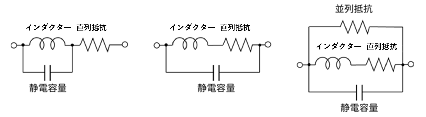
Three equivalent models of inductors are generally used as shown in the figure below. An inductor and a capacitance connected in parallel with a series resistor connected to it, a capacitance connected in parallel to both the inductor and the series resistance and a parallel resistance connected. It's a thing. All of them show almost the same characteristics.
A capacitance and an inductor connected in parallel will cause a self-resonant phenomenon at a certain frequency. Therefore, the image of the frequency characteristics is as shown in the figure below.
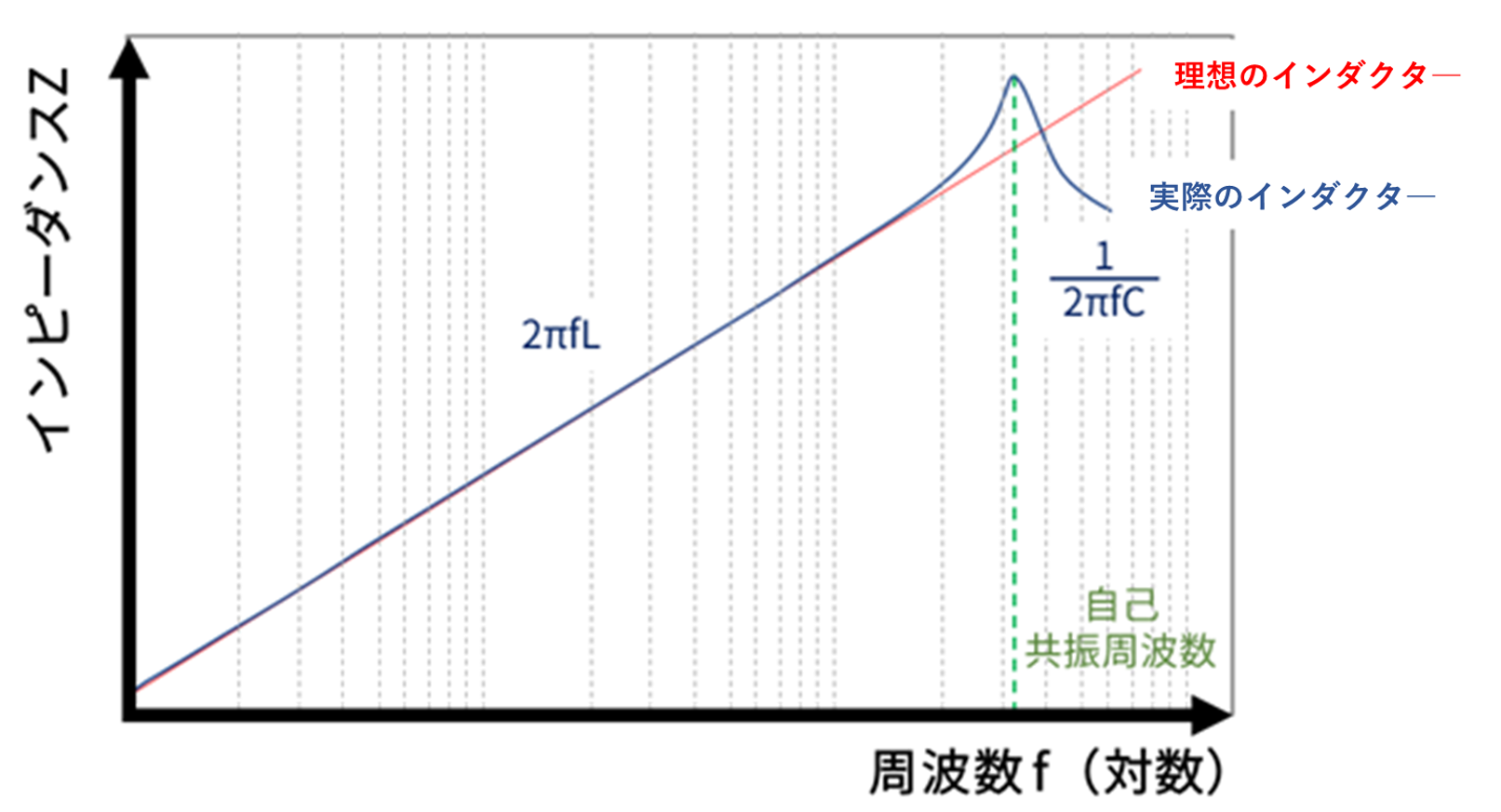
Up to the self-resonant frequency, it exhibits inductive characteristics (impedance increases as the frequency increases), and beyond the self-resonant frequency it exhibits capacitive characteristics (impedance decreases as the frequency increases), and above that frequency, the impedance decreases. will no longer function as a true inductor.
Therefore, when selecting inductors for high-frequency circuits and high-frequency modules, it is necessary to consider not only the required inductance value, but also the self-resonant frequency relative to the operating frequency.
Since the inductor does not function at frequencies higher than the self-resonant frequency, select an inductor with a higher self-resonant frequency than the switching frequency of the power supply IC.
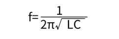
The self-resonant frequency is obtained by the following formula, so the smaller the L value, the higher it becomes.
"point"
- In actual inductors, self-resonance occurs due to stray capacitance.
- It exhibits inductive characteristics up to the self-resonant frequency, and exhibits capacitive characteristics beyond the self-resonant frequency.
- Since the inductor does not function at frequencies higher than the self-resonant frequency, select an inductor with a higher self-resonant frequency than the switching frequency of the power supply IC.
- The smaller the L value, the higher the self-resonant frequency.
4. Types of inductors
Power system inductors can be classified according to their characteristics, depending on whether they are classified by magnetic material or by the state of magnetic flux generated.
(1) Classify by magnetic material
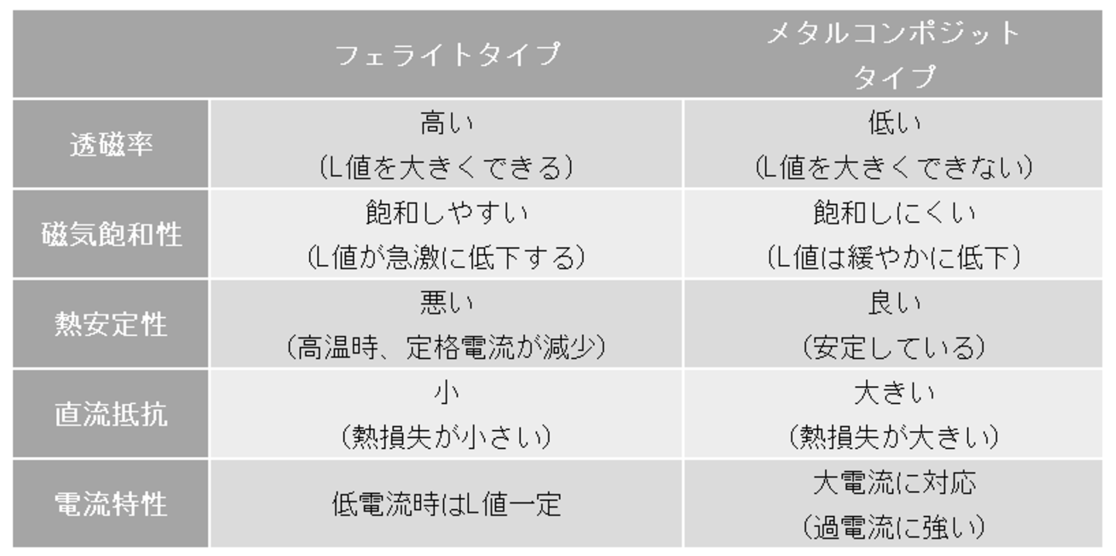
There are two types of magnetic (core) materials for inductors: ferrite and metal composite. Until now, ferrite has been popular, but in recent years, the metal composite type using a metal magnetic material has been attracting attention.
The metal composite type has better magnetic saturation characteristics and thermal stability than the ferrite type. On the contrary, the ferrite type has excellent DC resistance. A summary is given in the following table.
(2) Classify by the state of magnetic flux
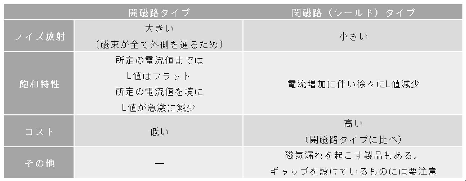
There are two types of power system inductors: the open magnetic circuit type and the closed magnetic circuit (shield) type.
When a magnetic toroidal core (doughnut-shaped core) is wound and a current is passed through it, the magnetic flux circulates inside the core. Such a magnetic circuit is called a closed magnetic circuit. When a rod-shaped or drum-shaped core is used, the magnetic flux exits from the inside of the core, becomes leakage magnetic flux, and forms a loop that returns to the core again. This is called an open magnetic path.
If leakage magnetic flux is magnetically coupled with other coils or wiring patterns, it will cause noise. Therefore, the open magnetic circuit type has larger radiation noise. However, even with the closed magnetic circuit type, there are some products that have a gap and cause magnetic leakage, so you need to be careful.
Due to the difference in magnetic structure, there is a difference in saturation characteristics between a closed magnetic circuit and an open magnetic circuit. Therefore, there will be differences in the DC superimposition characteristics. In the closed magnetic circuit, the L value gradually decreases as the DC superimposed current increases. On the other hand, in the case of an open magnetic circuit, the L value is relatively flat up to a predetermined current value against an increase in DC superimposed current, but the L value tends to decrease sharply after the predetermined current value. I have. However, the tendency of the curve changes depending on the properties of the magnetic material used.
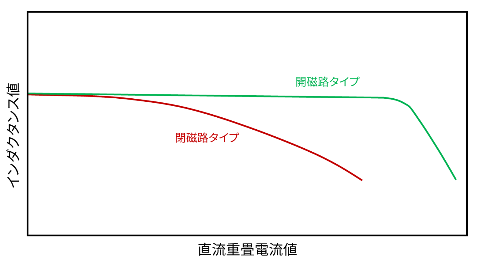
A summary is given in the following table.
Improve your circuit design skills by understanding the characteristics of discrete components!
In recent years, the design period has become tight due to the early introduction of products to the market. Even with proven designs and reference designs, discrete components must be selected for circuit optimization. At that time, this technical article will tell you the selection method that will be your base.