- Semiconductor BusinessHOME
- Products and Services of Macnica,Inc.
-
technical information

-
Events and Seminars
- Handling Manufacturer
- Support
- Inquiry
- Click here to purchase products
- Semiconductor business e-mail magazine registration
![]()
![]() Narrow down by specifying conditions
Narrow down by specifying conditions
現在2189件がヒットしています。check

This series uses reference circuits for evaluation boards for converter ICs to explain important characteristics in selecting various discrete components.
When explaining, use LTspice for individual characteristics, change the constants of the parts or the parts themselves, check the changes on the circuit with simulation waveforms and calculated values, and explain the relationship between the characteristics and the circuit. increase.
This time, I will explain how to select the inductor required for a synchronous rectification type buck converter circuit, and how to select the inductor characteristics, using LTspice simulations to confirm the effect of inductor characteristics. .
In this first part, we will explain "the role of inductors in power supply circuits" and "inductance value: L". In Part 2, we plan to explain "Rated current: Isat, Itemp," "DC resistance: Rdc," "Self-resonant frequency: SRF," and "Types of inductors."
Also, please refer to the following for LTspice and evaluation kits used in the explanation.
[How to download / use LTspice]
・ LTspice download page (link to Analog Devices website)
*If you want to know how to use LTspice, please check the Company article below.
[Evaluation board used/mounted regulator/board purchase information]
・ LT8609A Synchronous Buck Regulator (link to Analog Devices website)
・Evaluation board: DC2958A (link to Analog Devices website)
・Evaluation board DC2958A is available at Macnica-Mouser.jp. (Link to Macnica-Mouser.jp)
(Note)
This article does not describe how to select peripheral components (inductors) for the above converter IC LT8609. It is used as a sample circuit example to check the characteristics of the inductor on LTspice.
table of contents
Part 1
・ Role of inductors in power circuits
・ Inductance value: L
Part 2
・Rated current: Isat, Itemp
・DC resistance: Rdc
・Self-resonant frequency: SRF
・Inductor type
1. Role of inductors in power circuits
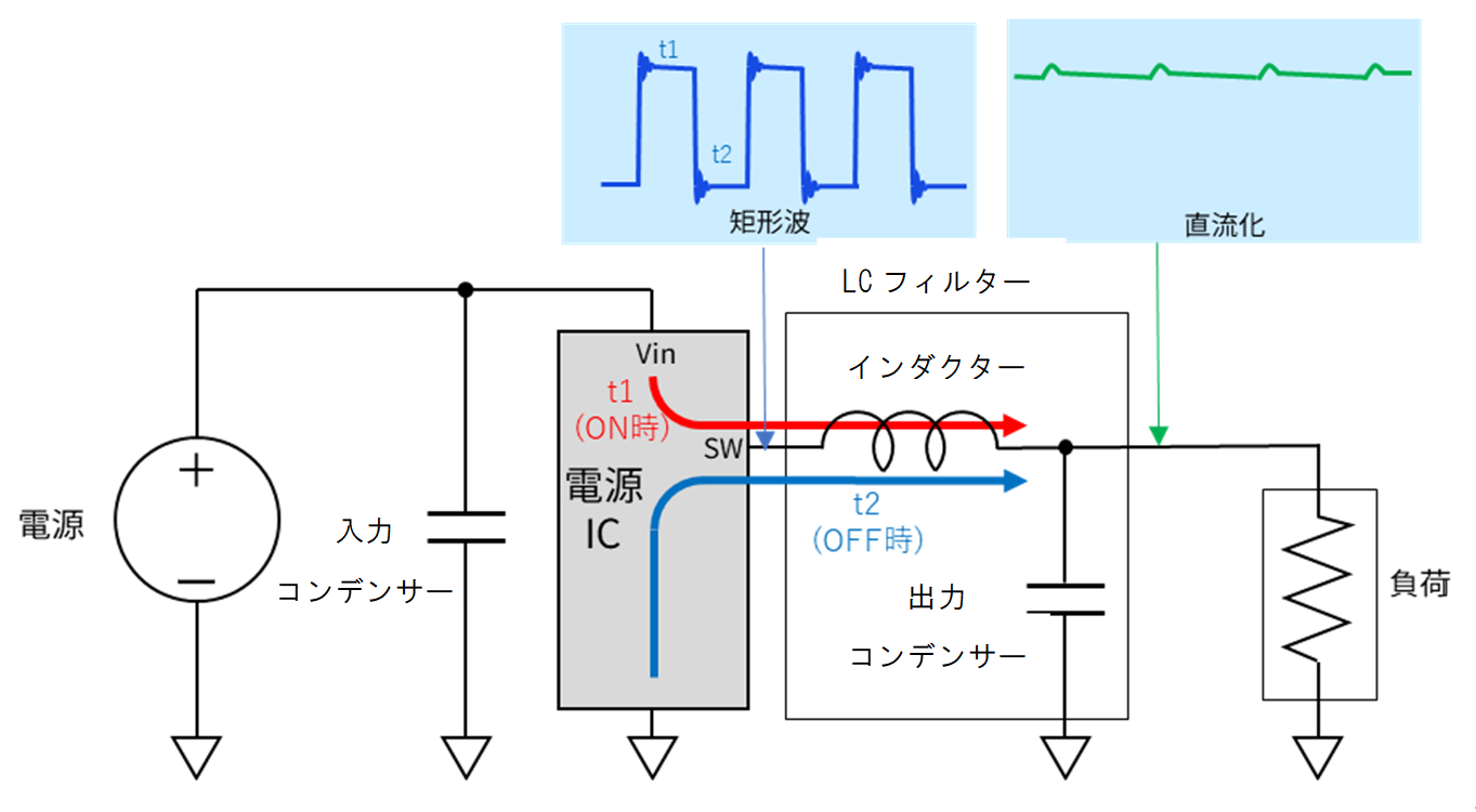
Inductors, one of the components of power supply circuits, play an important role along with resistors and capacitors. When using an inductor in a DCDC converter, the time (t1) when current is supplied from the power supply IC and the time (t2) when it is not supplied alternately. Magnetic energy is accumulated in the inductor at the same time as the current is supplied from the IC to the load side.
During the time when no power is supplied from the IC side, the magnetic energy accumulated in the inductor supplies current to the load side.
In this way, inductors have the role of storing magnetic energy and supplying current to the load side. (Note that the ratio of t1 and t2 determines the output voltage.)
In addition, along with the capacitor, it also has the role of smoothing the rectangular wave output from the power supply IC and converting it to direct current (LC low-pass filter).
"point"
- Supply current to the load as a current source that uses the properties of an inductor (when current flows, it tries to maintain its state)
- Square wave output from power supply IC is smoothed and converted to DC.
2. Inductance value: L
When the current flowing through the inductor changes, an induced electromotive force is generated. The magnitude of the electromotive force can be expressed by the following formula.
V = Ldi/dt
In relation to power supplies, Δi /Δt=V/L, which is a modified version of this formula, is often used.
That is, the change in current (Δi/Δt) when a voltage (V) is applied to the inductor is inversely proportional to the inductor value (L).
The L value is a very important parameter that affects inductor ripple current and load response characteristics. As the current flowing through the inductor increases, magnetic saturation occurs in the magnetic material and the L value decreases. This is called "DC superimposition characteristics". The L value listed in the datasheet is the value when the DC superimposition current is 0A.
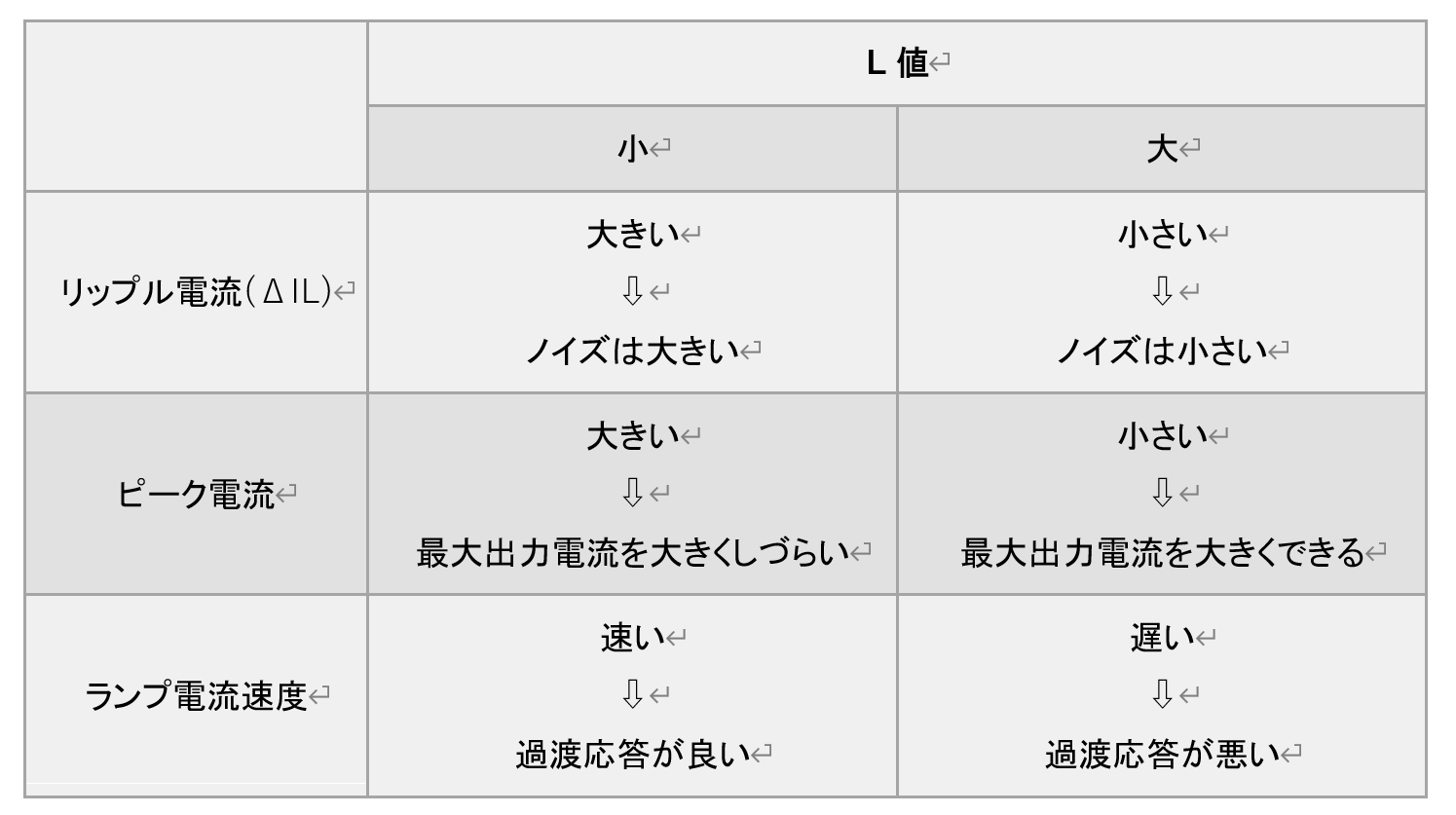
In general, the larger the L value, the smaller the ripple current (ΔIL) and the smaller the noise (ripple voltage). In addition, the peak current becomes smaller, and the current does not easily exceed the threshold value of the overcurrent protection function (explained later) of the power supply IC, making it difficult for the overcurrent protection function to operate, and the maximum output current can be increased. However, since the lamp current speed is slow, the amount of current increase per unit time is small, resulting in poor transient response.
The opposite is true for all small L values. A summary is given in the following table.
From the specifications of the power supply IC, the appropriate L value can be obtained from the following formula.
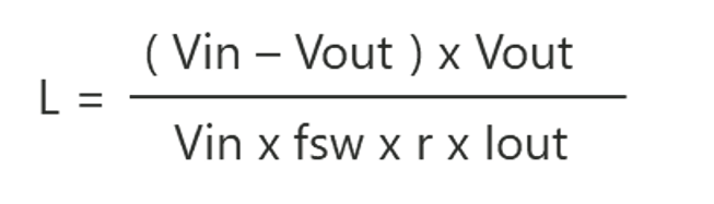
Vin: Input voltage Vout: Output voltage fsw: Switching frequency Iout: Load current
r: Current ripple ratio (Appropriate value is 0.3 to 0.4)
The current ripple ratio r can be obtained from the following equation.
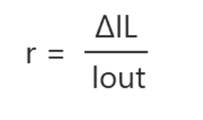
ΔIL is the inductor ripple current. It is expressed by the following formula.
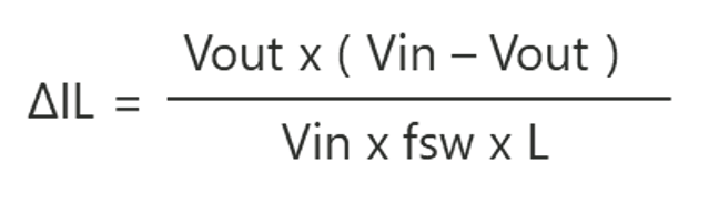
(From this equation we can see that the ripple current is inversely proportional to the value of L)
However, since the data sheet of the power supply IC describes the appropriate L value, it is recommended to refer to the manufacturer's recommended reference circuit when selecting.
(1) Confirmation of inductor current
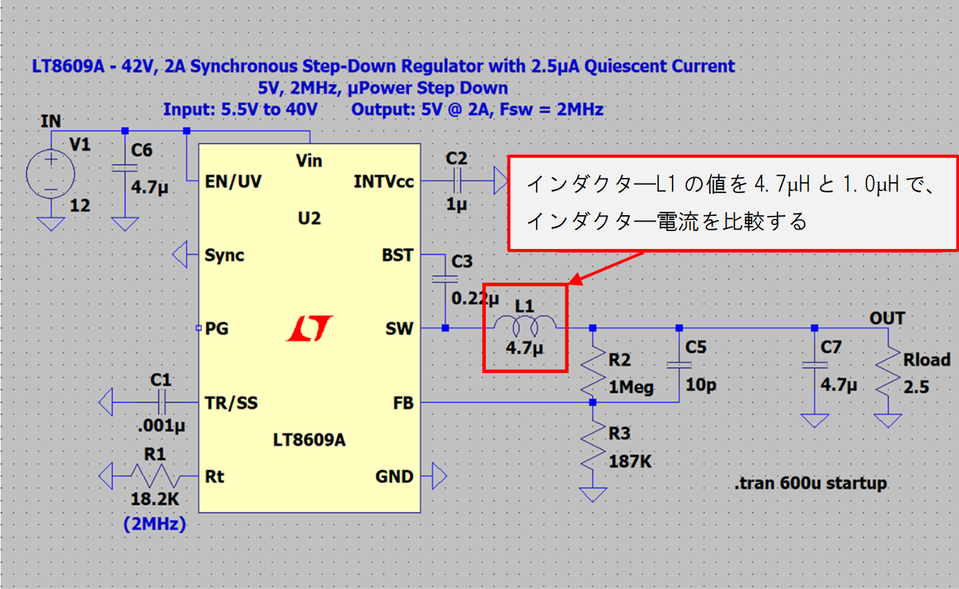
First, check the effect of the L value on the inductor current by simulation.
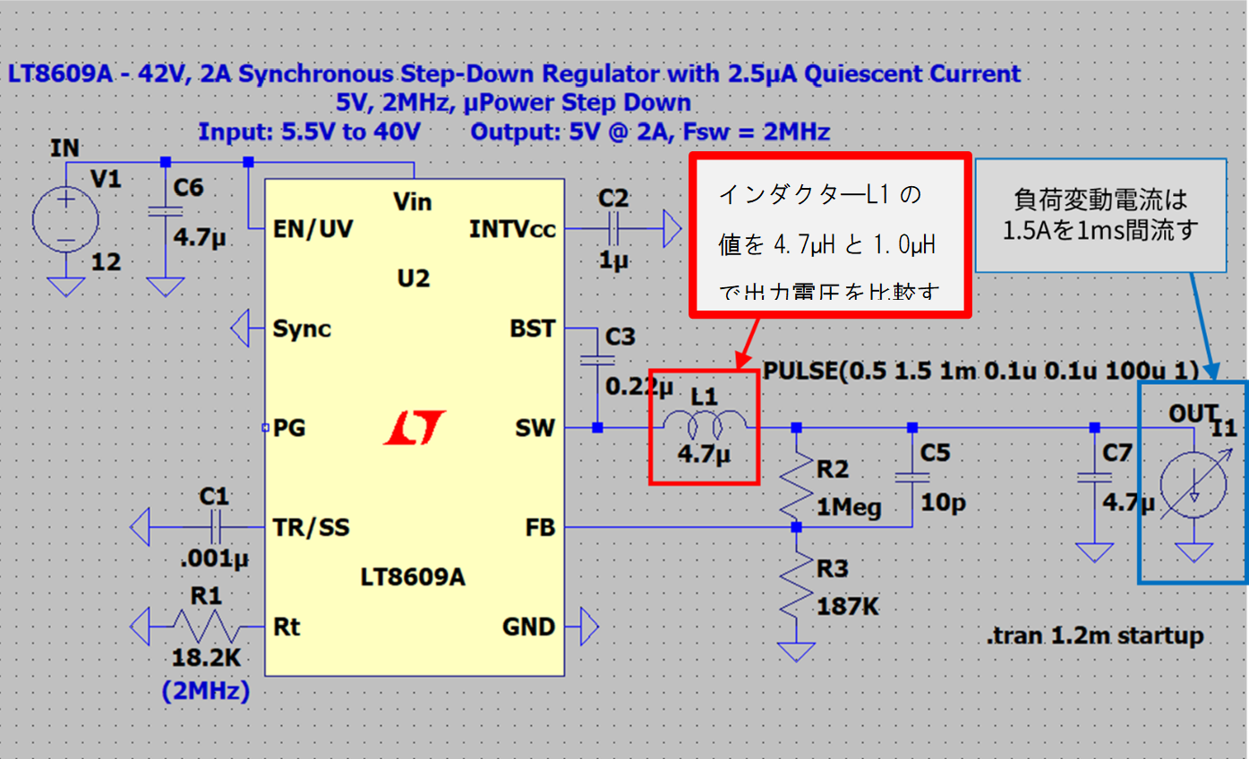
The circuit to be simulated is shown in Figure 1. For this circuit configuration, 2.2 μH is the proper value for L1, but here we will compare the following two values, which are extremely different, in order to clarify the difference.
Compare the inductor current with a relatively large value of 4.7 µH for inductor L1 and a relatively small value of 1.0 µH.
The simulation results are as follows.

The ripple current (ΔIL) is about 0.32A for 4.7µH and about 1.50A for 1.0µH.
It can be confirmed that the relationship between the L value and the ripple current (ΔIL) is inversely proportional.
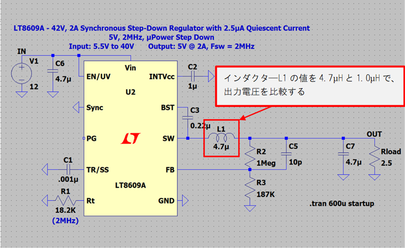
(2) Confirmation of output voltage status
Next, change the L value and check the state of the output voltage.
The circuit to be simulated is shown in Figure 2. The circuit configuration is the same as in Fig. 1, but the comparison target is the output voltage. Again, compare inductor L1 values of 4.7 µH and 1.0 µH.
The simulation results are as follows.
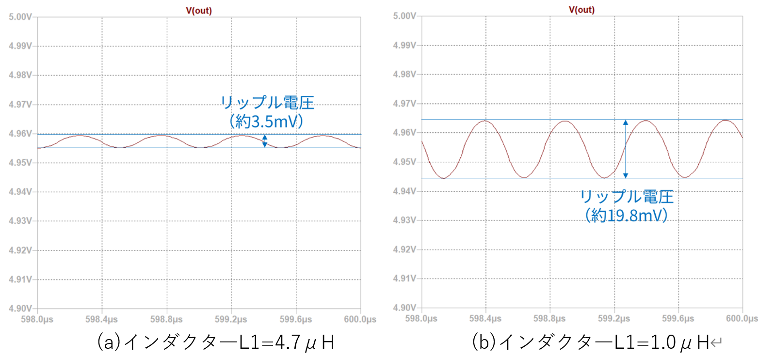
The ripple voltage is about 3.5mV for 4.7µH and about 19.8mV for 1.0µH.
It can be seen that a large inductor current affects the ripple voltage of the output voltage. To reduce the ripple voltage when the inductor value cannot be changed, the capacitance of the capacitor must be increased.
(3) Confirmation of transient response state
Now let's change the L value and check the transient response condition. The load fluctuation current conditions are simulated under the conditions of increasing from 0.5A to 1.5A in 0.1us, flowing 1.5A for 1ms, and decreasing from 1.5A to 0.5A in 0.1us.
The circuit to be simulated is shown in Figure 3. The basic circuit configuration is the same as Figures 1 and 2, but a current source is connected as a load to flow the load current. Again, compare the output voltages with inductor L1 values of 4.7 µH and 1.0 µH.
The simulation results are as follows.
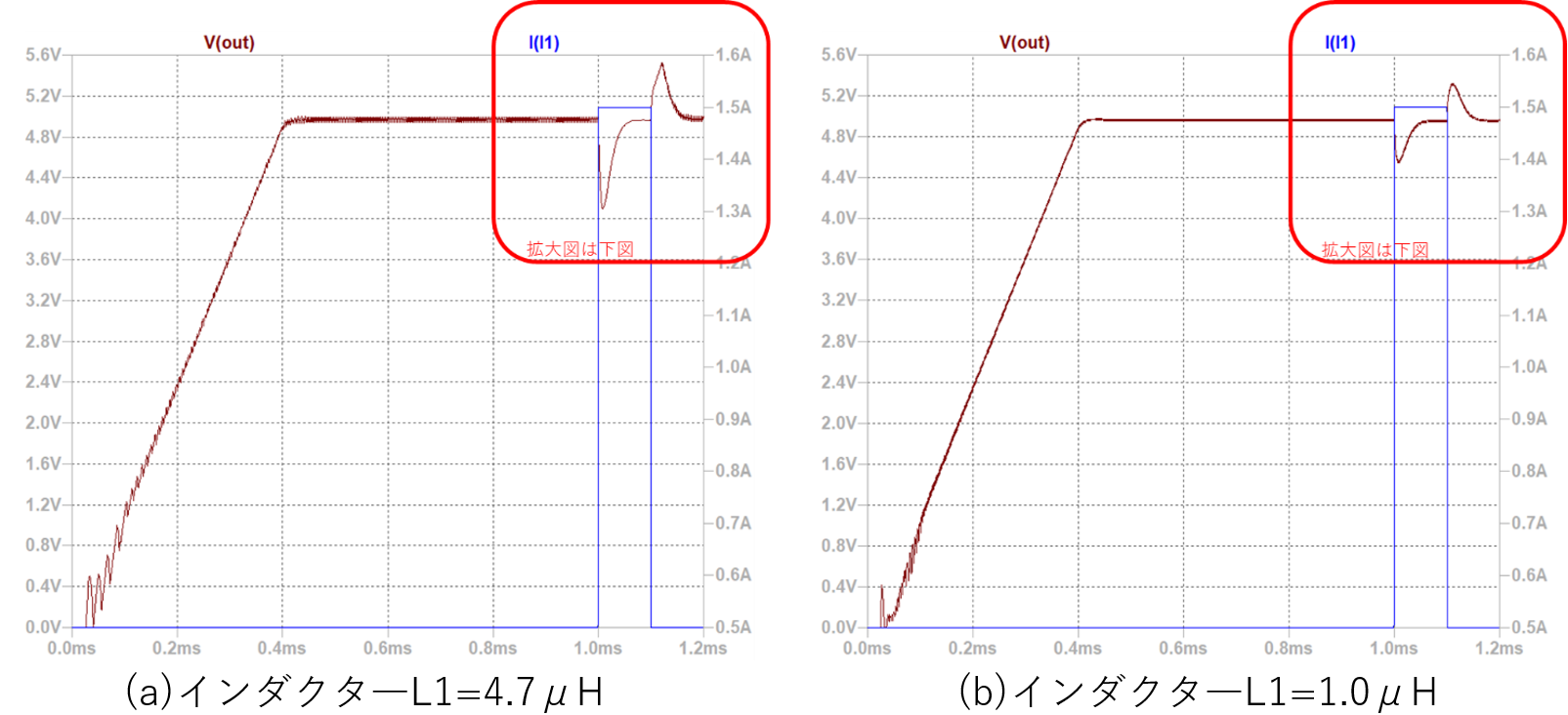
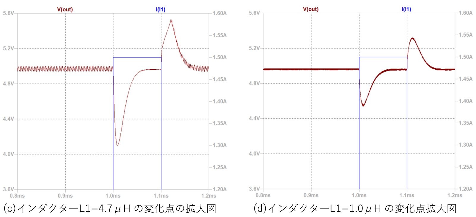
As mentioned in the lamp current speed column of Table 1, a large inductor results in poor transient response (slow response speed). Comparing the output voltages for 4.7 μH and 1.0 μH during periods when the load current fluctuates abruptly, it can be seen that the 4.7 μH case has larger fluctuations. From this we can see that the inductor value affects the state of the output voltage during transient response.
(4) Confirmation of increased load current
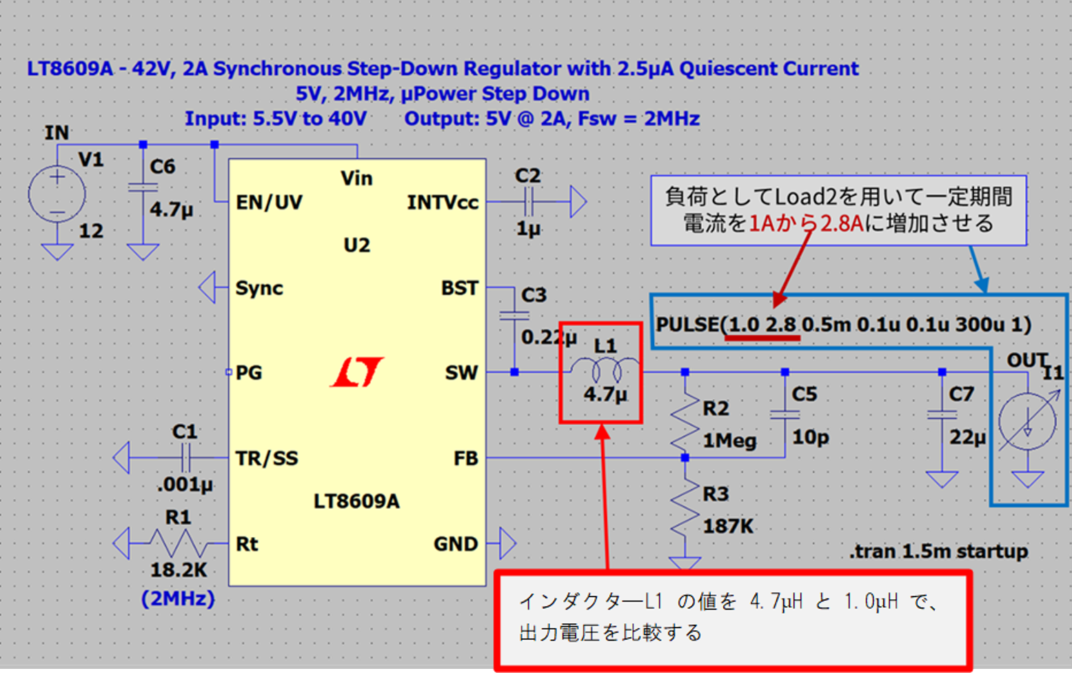
What if the load current is higher? Let's use a simulation to check what kind of phenomenon occurs when the load current is 2.8A, which is larger than the 1.5A mentioned earlier.
The circuit to be simulated is shown in Figure 4. Increase the current from 1A to 2.8A for a period of time using Load2 as the load. Again, compare the output voltages with inductor L1 values of 4.7 µH and 1.0 µH.
Before starting the simulation, as preliminary knowledge, we will explain the over current protection (OCP) function when the output current of the power supply IC increases.
The overcurrent protection function is a function that stops the output of the power supply IC when the output current becomes abnormally large due to some accident such as an output short circuit. This prevents deterioration of power supply IC characteristics, malfunction, and damage due to excessive current. The method of detecting overcurrent and the method of stopping the output differ depending on the product.
In this simulation, the load current is large, so the overcurrent protection function of the power supply IC (this IC is a frequency foldback type: a method that limits the output current by lowering the oscillation frequency and reducing the minimum ON duty). may work.
For details on the overcurrent protection function, refer to the manuals (manuals, etc.) of each product.
(a) Inductor - simulation results for L1 = 4.7μH
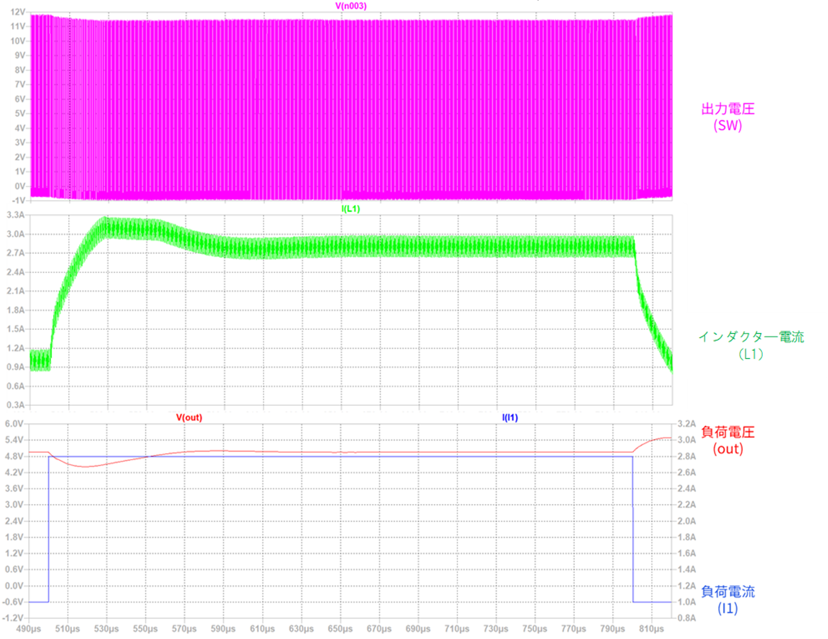
Immediately after the load current increases, the change in the load current is fast and the correction speed of the IC 's output voltage cannot keep up with it, so the voltage drops immediately after the load current increases rapidly, but the change in the inductor peak current is suppressed. , does not exceed the overcurrent protection threshold of the power supply IC. Therefore, the overcurrent protection function does not operate and normal operation continues.
(b) Inductor - simulation results for L1 = 1.0μH
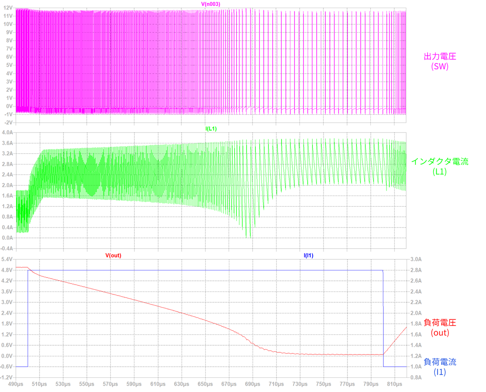
If the L value of the inductor is small, the ripple current increases, so if the load current suddenly increases, the inductor peak current also increases, the overcurrent protection function of the power supply IC is activated, and the output voltage drops. .
"point"
- The relationship between L value and inductor ripple current (ΔIL) is inversely proportional.
- A large inductor current affects the ripple voltage of the output voltage.
- The magnitude of the inductor current affects the state of the output voltage during transient response.
- If the L value of the inductor is small, the ripple current will increase, so if the load current increases, the inductor peak current will also increase, and the overcurrent protection function of the power supply IC will operate, resulting in an intermittent state with a low duty and a drop in the output voltage. do.
Improve your circuit design skills by understanding the characteristics of discrete components!
In recent years, the design period has become tight due to the early introduction of products to the market. Even with proven designs and reference designs, discrete components must be selected for circuit optimization. At that time, this technical article will tell you the selection method that will be your base.