- Semiconductor BusinessHOME
- Products and Services of Macnica,Inc.
-
technical information

-
Events and Seminars
- Handling Manufacturer
- Support
- Inquiry
- Click here to purchase products
- Semiconductor business e-mail magazine registration
![]()
![]() Narrow down by specifying conditions
Narrow down by specifying conditions
現在2173件がヒットしています。check

This is Sasaki in charge of power supply dock technology.
In this column, I would like to introduce some examples of problems related to power supplies that I encountered multiple times during various customer support sessions.
A customer contacted us and said, ``We are having trouble with a communication error with the FPGA transceiver.''
Is it OK to check only around the power supply circuit?

Only a few boards are having issues. .
I'm reviewing the power circuit diagram around the FPGA and the internal logic design, but I'm at a dead end without knowing the cause. . .

First, let's check all the power supply voltages on the board.
Check power supply voltage
yeah? what is this resistance?
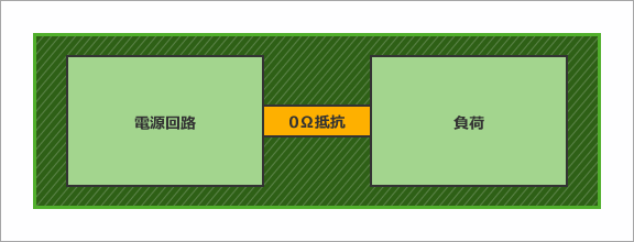
This is a 0 (zero) ohm resistor attached for debugging.
This disconnects and connects the power supply and the load.
I see.
(This is suspicious...)
Next, let's measure the voltage of the power supply related to the transceiver.
Could you please measure the power supply voltage at the terminal closest to the FPGA?
Measure the power supply voltage at the pin closest to the FPGA
Ah! The voltage has dropped by 100mV!
This does not meet the required specifications of FPGA. .
Oh really. Could you show me the inner layer pattern of this power supply?
Check the inner layer pattern of the power supply
So that's it.
(This is suspicious...)
I intend to make the power supply pattern as thick as possible, but is there any problem...?
(Is there a problem here too?)
Well, I found two problems.
The first is the 0 (zero) Ω resistor mentioned earlier. The wires are thin at this point.
The second is the number of through holes.
Many through holes are opened for other wiring, but this causes the power pattern to be thin (mesh pattern).
It seems that these two causes the resistance value to rise and the voltage to drop.

Even though it's a slight pattern change, is it such a severe problem?
I agree.
In particular, power supply circuits below 1.0V, such as transceiver power supplies, are greatly affected by voltage drops due to wiring patterns.
It is necessary to estimate the drop in advance and check that there are no problems with the wiring width.
Is that so. I would like to be more careful in the future.
Cause of power supply voltage drop
0 (zero) Ω resistors and through-holes make the wiring pattern narrower
The point of this time
For power supply circuits of 1.0V or less, it is necessary to estimate the voltage drop in advance!
(thereby determining whether the power request can be met)