- Semiconductor BusinessHOME
- Products and Services of Macnica,Inc.
-
technical information

-
Events and Seminars
- Handling Manufacturer
- Support
- Inquiry
- Click here to purchase products
- Semiconductor business e-mail magazine registration
![]()
![]() Narrow down by specifying conditions
Narrow down by specifying conditions
現在2153件がヒットしています。check

Limited quantity! BLDC motor set giveaway campaign underway
If you are an application designer using a BLDC motor, have you ever wanted to make your motor run more smoothly, quietly, with less power consumption, and with greater precision?
This time, we will introduce the ADI Trinamic™ series of motor drivers, which allow you to easily and freely achieve ideal motor operation.
Three drive methods for BLDC motors
There are three types of drive methods for BLDC motors: square wave voltage drive, sinusoidal voltage drive, and FOC drive (sinusoidal current drive). To precisely move the motor, it is important to control both the current and voltage so that they form sine waves. If the voltage applied is not of the appropriate magnitude and timing relative to the motor's rotation, power loss will occur, resulting in reduced efficiency.
|
Square wave voltage drive |
Sinusoidal voltage drive |
FOCdrive (sinusoidal current drive) |
|
| Control cycle/calculation load |
Every 60° commutation / low |
Every sine wave / in |
Per PWM / High |
| Position Sensor Resolution |
× |
△ |
〇 |
|
Total cost |
〇 |
△ |
× |
|
Speed and position control accuracy |
× |
△ |
△ |
| Vibration and noise |
△ |
〇 |
◎ |
| Drive efficiency (energy saving) |
× |
△ |
◎ |
| Motor voltage and current waveforms | 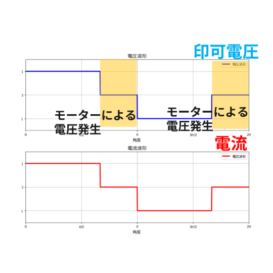 |
 |
 |
■ Square wave voltage drive
This is a simple configuration method that applies voltage every 60 degrees of commutation. The current waveform becomes nearly square, which leads to vibration and noise. It is easy to control, but the operation is rough and the efficiency is low.
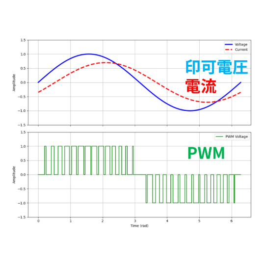
■ Sine wave voltage drive
It is more efficient and quieter than square wave voltage drive. It usually uses three Hall sensors to switch the current according to the detected rotation position. It rotates more smoothly than square wave voltage drive, but the efficiency is only medium because it generates unnecessary voltage.
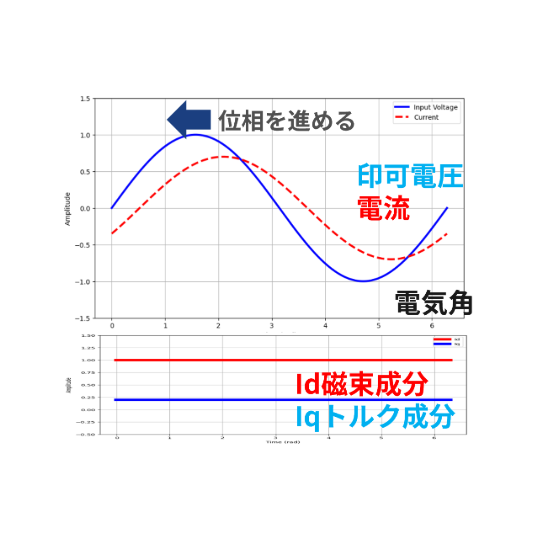
■ FOC drive
This method has higher resolution and is more efficient than sinusoidal voltage drive. It constantly monitors the current of all phases and applies voltage according to the motor's condition. This enables quiet, smooth operation with high efficiency.
FOC drive is particularly suitable for applications that require precise movement and high efficiency, such as robot arms, the tips of machine tools, and the undercarriage of AGVs (automated guided vehicles).
FOC faces the challenge of complex software
On the other hand, FOC drive requires complex calculations to analyze and control the motor's status in real time. This requires detailed software development, which has led to issues with development time. Furthermore, applications that control multiple axes, such as robot arms, require many high-performance processors such as DSPs (Digital Signal Processors).
The ADI Trinamic™ series BLDC driver introduced here (hereafter referred to as Trinamic ™) has a built-in FOC control function as hardware, enabling quiet, smooth, and energy-saving motor control with a light computational load.
Now let's take a closer look at the features of Trinamic™.
Trinamic™ solves your software development challenges
Example of Trinamic™ FOC system configuration for BLDC (with sensors)
The diagram below shows an example of a FOC control system for a BLDC motor using Trinamic™. Here we introduce a method using sensors.
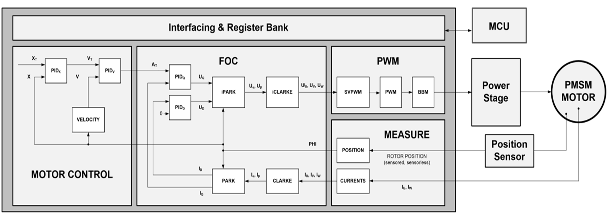
In addition to standard FOC control functions, Trinamic™ also has speed and position control functions built into the hardware. This means there is no need to implement motor control algorithms in the host MCU (Micro Controller Unit). Advanced control is possible simply by setting registers via SPI communication, etc. The power stage gate driver is also built-in, simplifying design.
Trinamic™ Design Benefits
By using Trinamic™, you can achieve the following benefits:
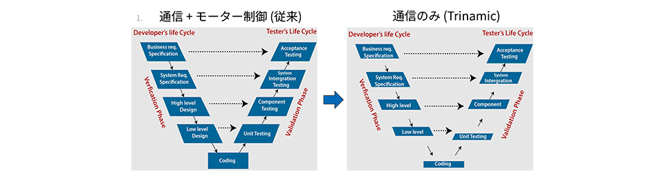
■ Software is simplified, reducing development time
Conventional FOC drives require huge development time because motor control functions are implemented as software. Changing specifications is also complicated, and even a simple change in coefficients requires extensive re-verification.
With Trinamic™, motor control is performed on the hardware side, so the software side is completed only through communication. This makes it possible to significantly reduce development time. In addition, parameters can be changed even during execution, allowing you to efficiently proceed with development while checking actual operation.
The ability to support a wide range of sensors ensures freedom of design, enabling precise motor control while reducing development time. This reduces software-related issues, improving the reliability of the entire system.
■ Downgrade your MCU to save money and save energy
By simplifying the software processing, the calculation load on the MCU is reduced. Because a high-performance MCU is no longer required, it is possible to use a lower-cost, lower-power MCU. This leads to cost reductions and energy savings.

■ No need for a separate motor control MCU
In conventional configurations, a control MCU was required for each motor driver. With Trinamic™, multiple motor drivers can be controlled using just the host MCU, reducing the number of components, board space, and costs.

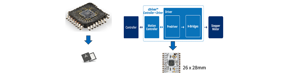
■ Peripheral components are built in, allowing for miniaturization of the board
Trinamic™ integrates all necessary peripheral components and gate drivers into the device, allowing for a simple circuit configuration and reduced board space.
Trinamic™ available in a variety of forms
Support development in a format that meets your needs
Trinamic™ is available in a wide range of products, from individual ICs to modules and motors, allowing you to flexibly select a solution according to your application requirements.
One module that stands out among these is a new type called "Motion Cookie ™."
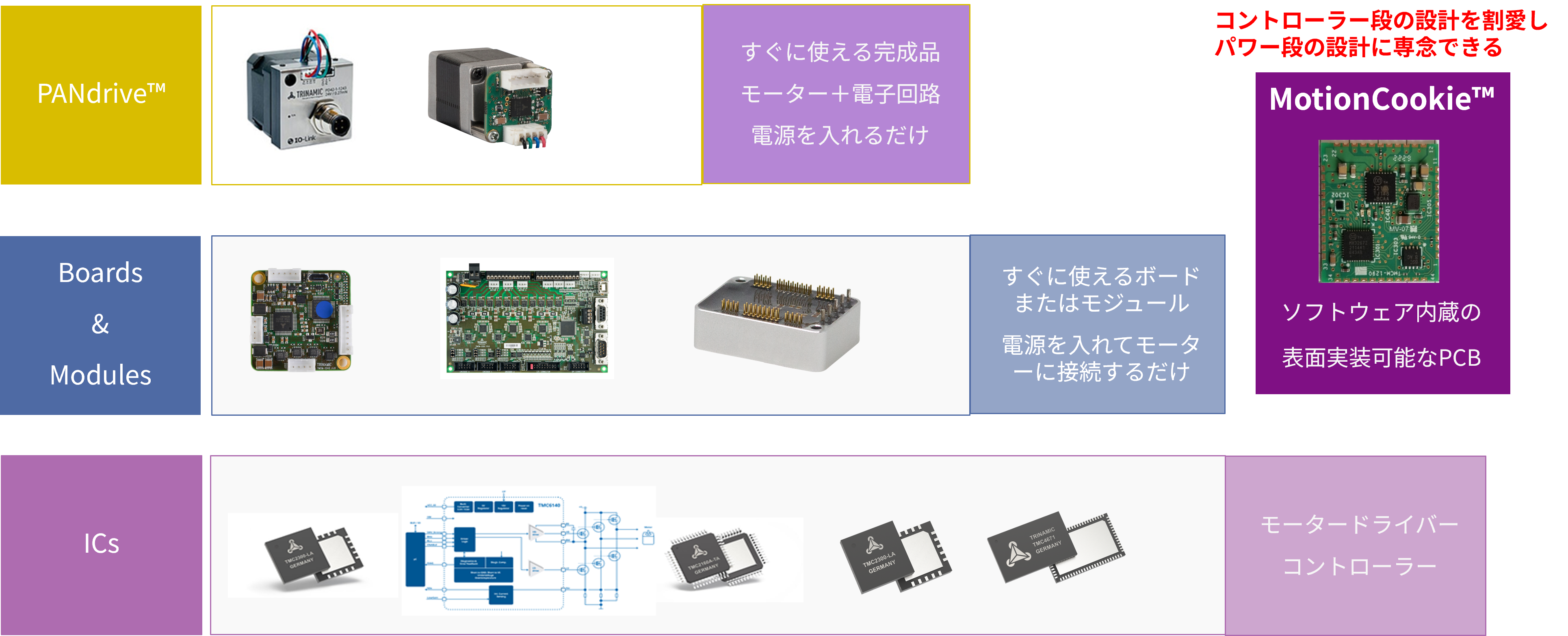
What are Motion Cookies™?
Motion Cookie™ is a small module that compactly integrates only the functions necessary for motor control and can be surface-mounted on a board. It incorporates an MCU, gate driver, and CSA (current sense amplifier), allowing for more efficient design than using a standalone IC.
The major difference from conventional modules is that it does not include a power stage, which allows us to both reduce design effort and utilize our own know-how in power stage design.

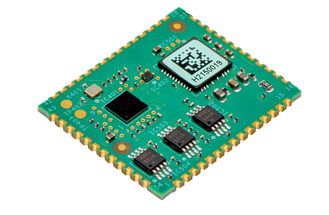
Motion Cookie™ product for BLDC "TMCM1690"
The TMCM1690 is a representative Motion Cookie ™ product for BLDC motors. It is equipped with a wide range of functions required for motor control and can meet a variety of needs.
TMCM1690 Features
The output stage transistor can be freely selected, and it can handle up to approximately 100A. It supports a voltage rating of 60V, so it can be used with 24V systems as well as 48V systems, which are in high demand in industrial applications. It supports a variety of feedback methods, including encoders and hall sensors, and its compact size of 27mm x 22.5mm makes it suitable for space-saving designs.
One of its distinctive features is its built-in advanced motion control functions, such as S-shaped ramps. Smooth acceleration and deceleration suppresses shaking and impact. Furthermore, "Lower Velocity PI" allows different parameters to be set for low and high speeds, enabling precise movement. It also comes equipped with braking and diagnostic functions.
■ Typical specifications
・Single-axis FOC servo controller gate driver module
・Compatible motors: 3-phase BLDC motors and DC motors
- Supply voltage range: +10V to +60V DC
Gate drive current: selectable from 0.5A/1.0A/1.5A, maximum 1.5A
- PWM frequency: Maximum 120kHz (can be set in the range of 20kHz to 120kHz)
- Equipped with an on-board current sense amplifier
・Supported position feedback: Incremental encoder (ABN), digital hall sensor, absolute encoder (SPI/SSI)
・Module size: Compact at 27mm x 22.5mm
Communication interfaces: UART (RS232), CAN, and EtherCAT® (SPI PDI)
Protocol support: TMCL, CANopen, CANopen, -over-EtherCAT (CoE)
■ Distinctive features
・Motion control
Supports both linear and S-shaped ramps. S-shaped ramps provide a linear change in acceleration, providing smoother operation and significantly reduced resonances in the system.
◦ The "Lower Velocity PI" function allows you to set different PI parameters at lower speeds, resulting in more precise control and smoother operation.
・Brake function
◦ Supports mechanical brakes that can use an independent power supply, and the release duty cycle, hold duty cycle, release period, etc. can be configured.
◦The brake chopper function dissipates the energy regenerated into the power line when the motor decelerates, preventing system damage.
Two types of brakes are supported: PWM brake and resistive/shunt brake.
・Diagnosis and protection
◦ IIT (Integral of Squared Current over Time) monitor function monitors energy consumption. If the limit is exceeded within a set time,
Stops the motor and sets the IIT error flag.
「TMCM-1690」
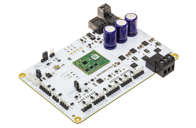
Evaluation board "TMCM1690-CAN-EVAL"
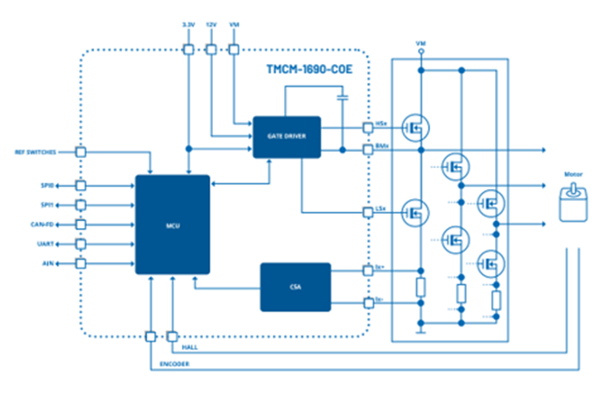
TMCM1690 Block Diagram
Easy setup using GUI
Trinamic™ can be easily configured using the GUI tool "TMCL-IDE." Simply follow the on-screen instructions and enter the operating conditions to complete the configuration. With plug-and-play functionality, you can configure the system while checking the actual operation, enabling you to achieve flexible motor control in a short amount of time.
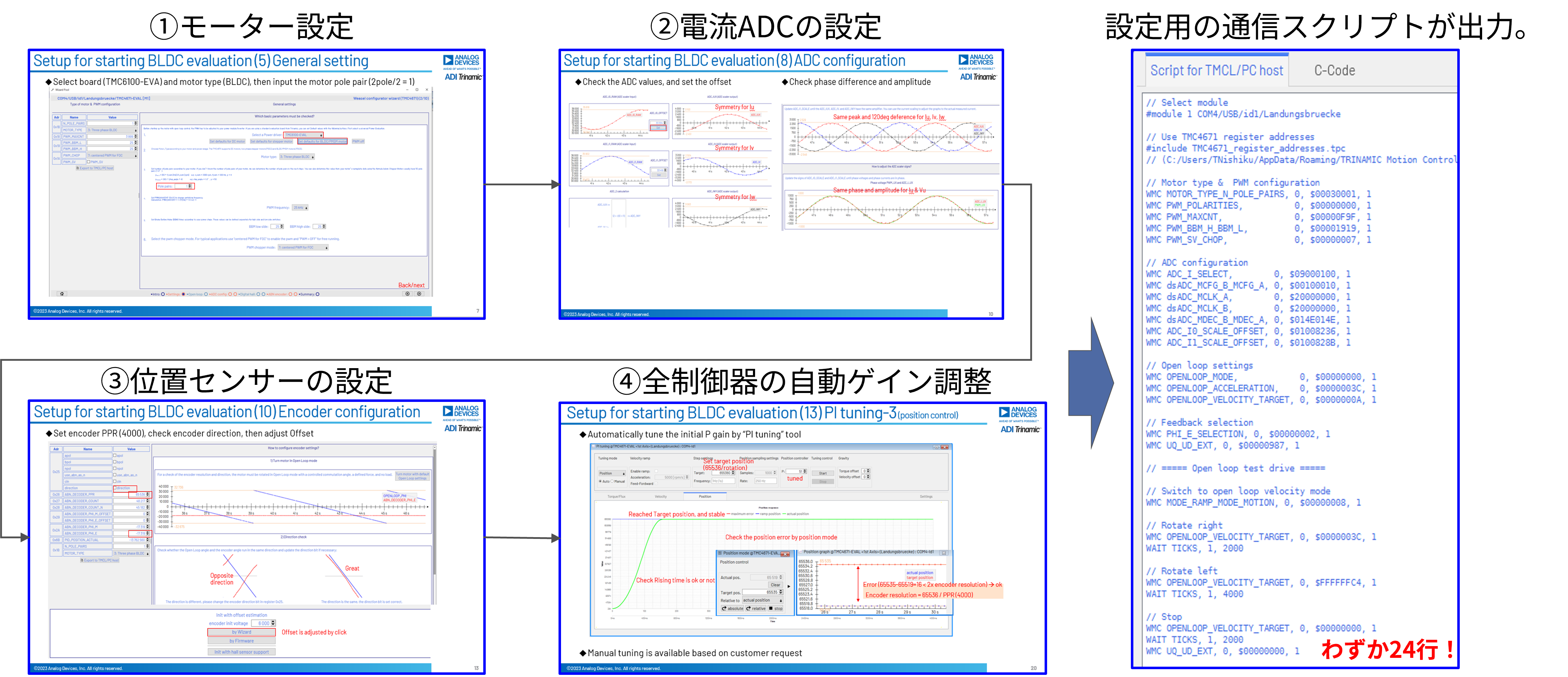
You'll quickly get used to the GUI tool "TMCL-IDE"!
Comparison with previous delivery formats
Below is a comparison table of the Motion Cookie ™ product TMCM1690 introduced here with the conventional module product (TMCM1617) and the IC alone (TMC4671). Please use this as a reference for the differences in functionality. The TMCM1690 can be used in a variety of situations, particularly in applications that require quiet, smooth operation and low power consumption.
| FOC |
〇 |
||
| Current Sense Function |
〇 |
× |
|
| Gate driver |
〇 |
× |
|
|
Position Feedback |
ABN, Digital Hall, Absolute encoder (SPI) |
ABN, Digital Hall |
ABN, Digital/Analog Hall, Analog Encoder |
| Motion Control |
〇 (linear ramp and S-shaped ramp) |
× |
|
| Supported protocol |
CANOpen, TMCL,CoE |
× |
|
| Package (mm) |
MotionCookie (27x22.5x3) |
Module (36.8x26.8x11.1) |
QFN76 (10.5x6.5) |
Application example
- 3D printer
- Industrial Automation
- Robots, AGVs
- Lab Automation
- Medical and Healthcare
- Battery-powered
- home automation
This time, we introduced the differences in BLDC motor drive methods and the features of Trinamic ™, which achieves precise FOC control with simple software.
FOC drive is effective for running BLDC motors quietly, smoothly, and with low power consumption. Trinamic ™ significantly reduces the software development required, a major challenge with FOC drive to date, and enables flexible motor control with just simple settings. The TMCM1690, offered as a Motion Cookie ™, has the advantage of allowing for flexible design of the power stage, making it easy to control advanced motion such as S-shaped ramps.
If you think you might be able to use it in your own application, why not start by evaluating it?
Please feel free to contact us.
Click here to purchase products
Click here for manufacturer site/other related links
Inquiry
If you have any questions regarding this article, please contact us below.
Analog Devices Manufacturer Information Top
Analog Devices Manufacturer Information If you would like to return to the top page, please click below.