- Semiconductor BusinessHOME
- Products and Services of Macnica,Inc.
-
technical information

-
Events and Seminars
- Handling Manufacturer
- Support
- Inquiry
- Click here to purchase products
- Semiconductor business e-mail magazine registration
![]()
![]() Narrow down by specifying conditions
Narrow down by specifying conditions
現在2149件がヒットしています。check

Waveform Observation
When we measured the efficiency, we found that there was a sudden drop in efficiency in some parts of the pre-review board (white board).
This time we will consider the cause of this!
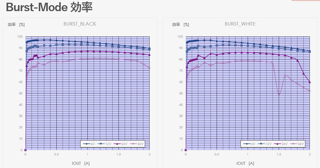
The only difference between the pre-review board (white board) and the post-review board (black board) is the board pattern.
For more details, please see "Creating a power supply with a homemade printed circuit board! (2)".
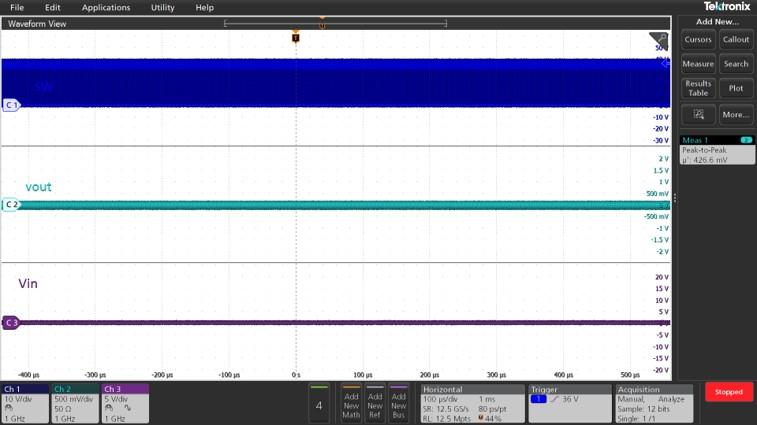
First, we observed the waveform around 36V-1.5A, where the efficiency on the white board drops sharply.
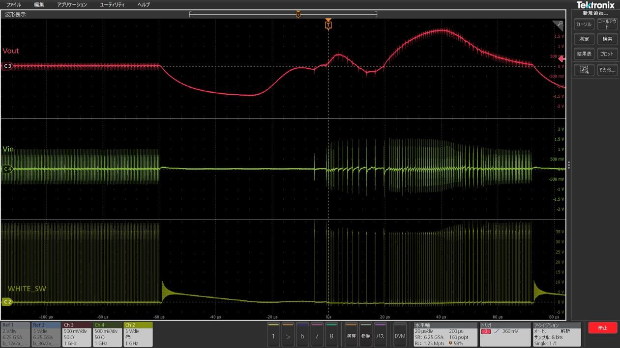
The waveforms, from top to bottom, are the "output node voltage," "input node voltage," and "switching node voltage." You can see that switching is interrupted midway. This may be the cause of the drop in efficiency.
The switching stop hypothesis
There are four possible causes for switching operation to suddenly stop:
- Overcurrent protection (OCP): The load current exceeds the allowable range, causing the protection circuit to activate and stopping switching.
- Overvoltage protection (OVP): The output voltage exceeded the specified value, causing the overvoltage protection to activate and stopping switching.
- Overtemperature protection (OTP): The converter became excessively hot and thermal shutdown was activated.
- Input voltage undershoot (UVLO): The input voltage falls below the specified lower limit and switching stops.
First, we were able to eliminate the causes of OCP, OVP, and UVLO because we were able to confirm that none of the voltage or current limits had been reached. Furthermore, when we compared the waveforms with those when the overcurrent protection (OCP) was activated, the characteristics did not match.
The only remaining possibility is "thermal shutdown." So how can we be sure that thermal shutdown is the cause?
Is this due to a thermal shutdown?
First of all, when does a "thermal shutdown" occur?
According to the datasheet, when the IC junction temperature exceeds 150°C, the thermal shutdown is activated as a protection function. This means that if the IC is cooled so that the junction temperature does not reach 150°C, the thermal shutdown should be avoided!
Furthermore, if cooling the board eliminates the intermittent switching phenomenon, it can be confirmed that the problem was caused by thermal shutdown. To verify this hypothesis, it is necessary to observe the waveform while cooling the entire board. This is where a "thermostatic chamber" comes in handy. A thermostatic chamber is a device that keeps the internal temperature constant within a set range and is used for temperature testing, characteristic evaluation, or storage of materials and products.
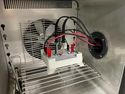
Measurement in a thermostatic chamber
As shown above, the board was placed in a case and placed in a thermostatic chamber. The temperature inside the chamber was set to -10°C and the waveform was measured.
The waveforms compared with those taken at room temperature are shown below.
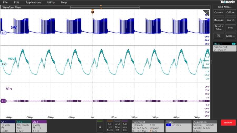
In the room temperature environment, switching stopped about 10 seconds after startup, but in the -10°C environment, switching continued without interruption even 3 minutes after startup!
Now we have determined that thermal shutdown is the cause!
In our next post, we will take a more in-depth look at the efficiency differences between the two boards.
We'll take a closer look at what factors are influencing this, so stay tuned!
Universal board/printed circuit board list
■Universal board edition
・ I made a DC/DC converter using a universal board (1)
・ I tried making a DC/DC converter using a universal board (2)
・ I tried making a DC/DC converter using a universal board (3)
・ I made a DC/DC converter using a universal board (4)
■Printed circuit board edition
・ Create a power supply with your own printed circuit board! (1)
・ Create a power supply with your own printed circuit board! (2)
・ Create a power supply using a homemade printed circuit board! (3)
・Create a power supply using a homemade printed circuit board! (4)
・ Create a power supply using a homemade printed circuit board! (5)