- 半導体事業HOME
- マクニカの製品・サービス
-
技術情報

-
イベント・セミナー
- 取扱メーカー
- サポート
- お問い合わせ
- 製品購入はこちら
- 半導体事業のメルマガ登録
![]()
![]() 条件を指定して絞り込む
条件を指定して絞り込む
現在2189件がヒットしています。check

はじめに
LTspiceを使ってみよう - 導入編 では、LTspiceの概要と簡単な機能紹介をさせて頂きました。
本記事では、具体的なLTspiceの始め方、基本的な操作方法を、簡単な回路設計をおこないながら説明します。
もしLTspiceを今から始められる方でしたら、以下の一覧から「基本編」を見ることをお勧めします。
また、基本的な回路の書き方から実行方法までを動画で見たいという方がいましたら、個人情報入力不要のオンデマンドセミナーがありますので、ご興味がありましたらぜひご覧ください。セミナーの詳細資料に関してもアンケートご記入の方に提供しています。
概要
電源回路においてSWのON/OFF時にリンギングが発生した場合の対策としてRCスナバ回路がよく使用されます。
LTspiceを用いた降圧コンバーター回路を題材にして、スナバ回路の定数検討の手順や効果を検証します。
検証回路
アナログ・デバイセズ社のLTC7803を例にして図1の回路を使用し検証します。
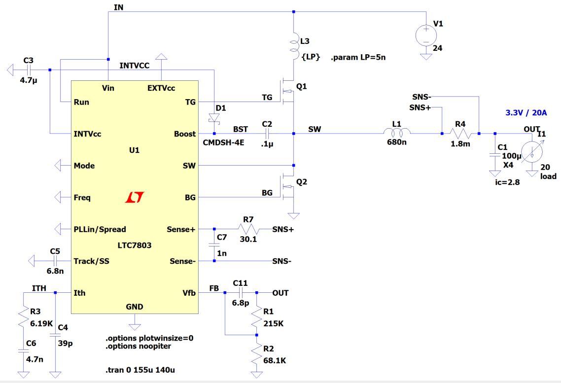
図1:検証回路
入力電圧:24V
出力電圧:3.3V
出力電流:20A
SW周波数:375kHz
スナバ回路定数検討の手順
スナバ回路の定数を検討には以下の方法を使用します
1.波形を確認しリンギング周波数(f)を求める
2.容量のみを追加してリンギング周波数の半分となるスナバ容量Csを調査する
スナバ容量Csはリンギングを生成している寄生容量の3倍になります
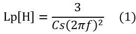
3.スナバ容量Csを用いて寄生インダクタンスを式(1)から求める
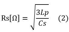
4.スナバ抵抗Rsを式(2)から求める
手順1:波形を確認しリンギング周波数(f)を求める
LTspiceを用いて図1の回路でSW1の波形を確認しリンギング周波数を確認します。
結果を図2に示します。リンギング周波数は約61MHzとなっています。
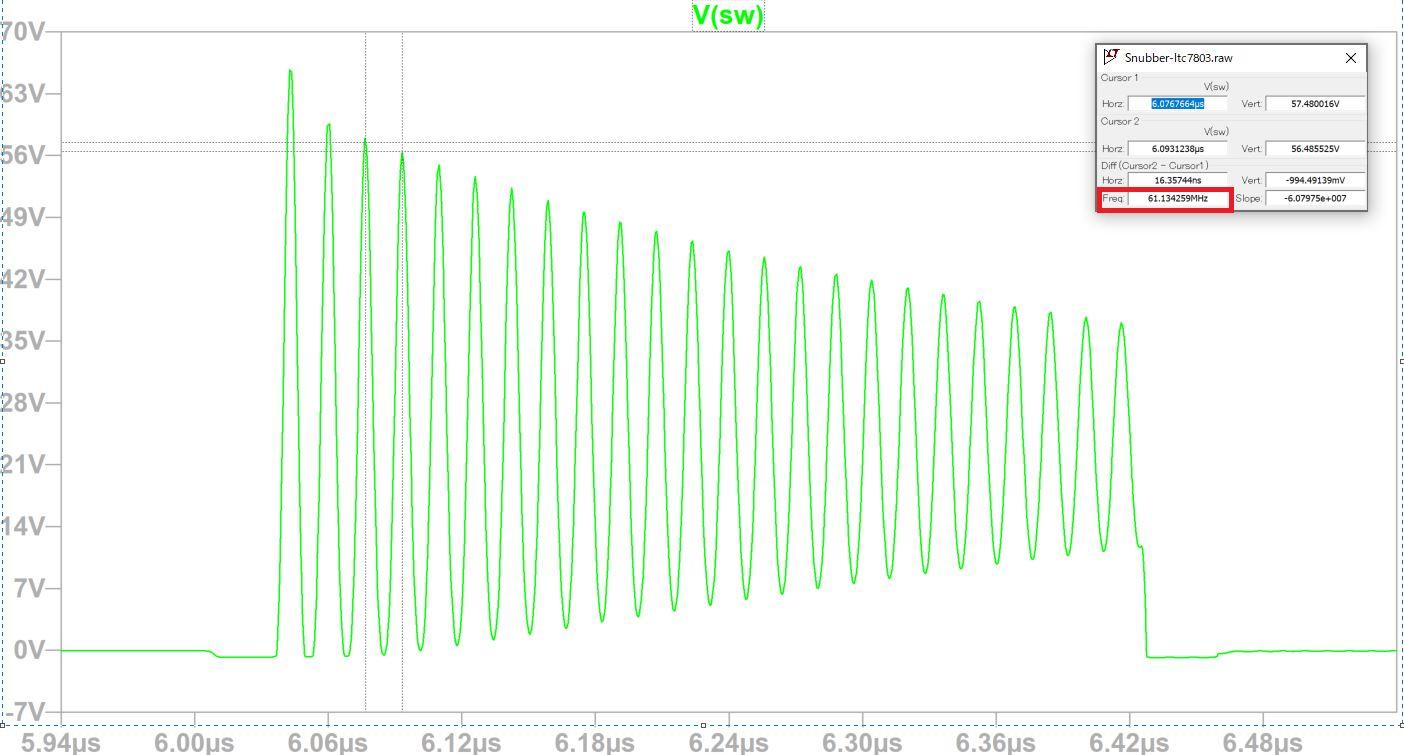
図2:リンギング周波数の確認
手順2:容量のみを追加してリンギング周波数の半分となるスナバー容量Csを調査する
図3のようにQ2と並列に容量を追加してシミュレーションをおこないます。
定数のシミュレーションでは「.step」コマンドを使用することで複数の定数を段階的に変化させてシミュレーションをおこなうこともできます。
「.step」コマンドについてはこちらの記事を参考にしてください。
LTspiceを使ってみよう -「.step」でパラメーターを変化させてみよう
今回の回路では図4の波形のようにCs=3900pFでリンギング周波数のほぼ半分となる結果が得られました。
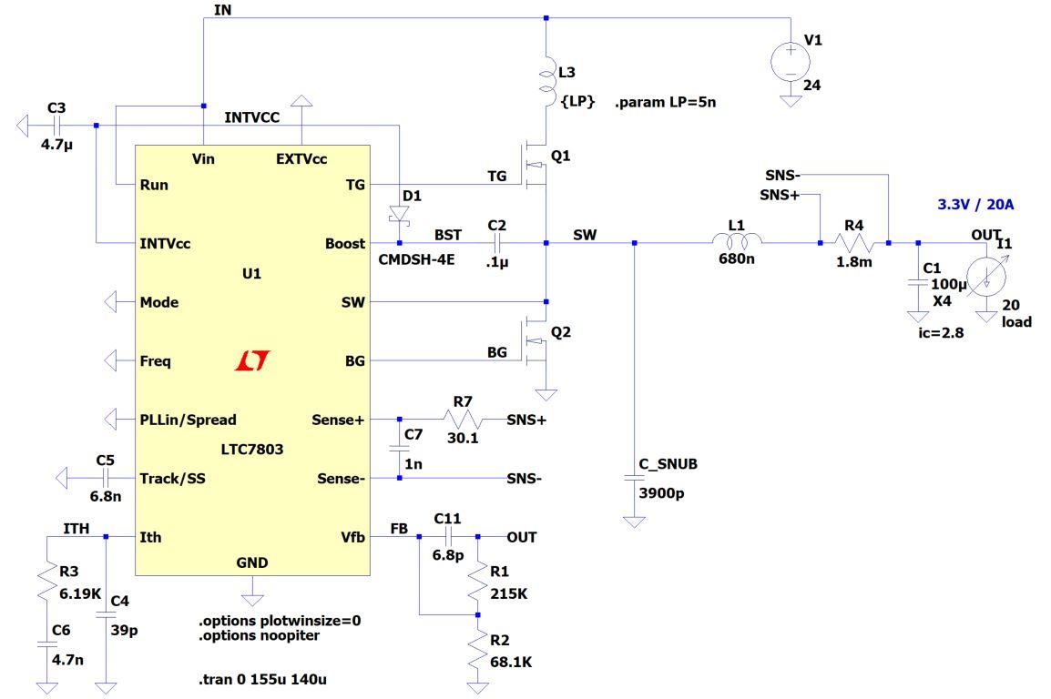
図3:スナバ容量の検証回路
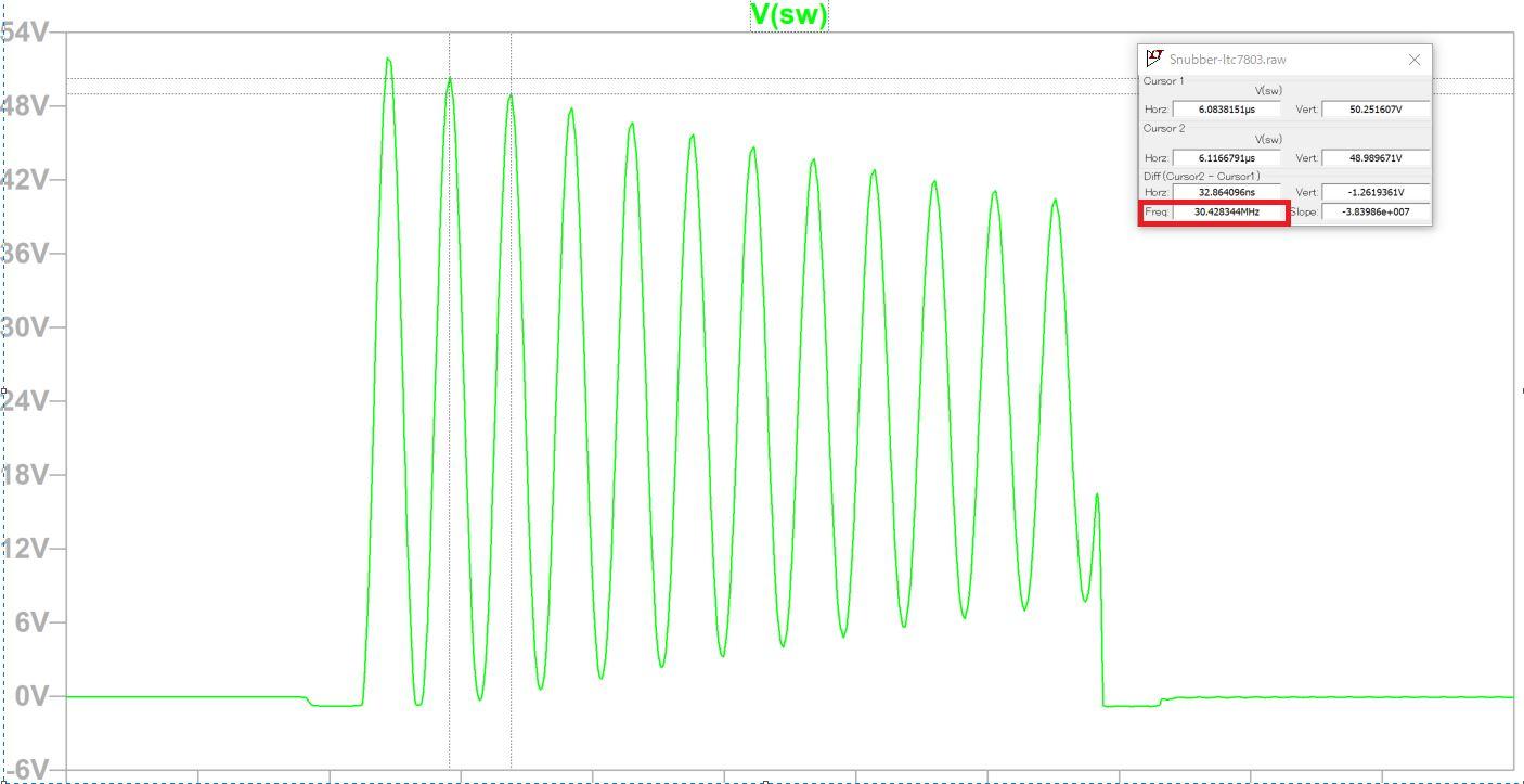
図4:図3の回路におけるシミュレーション結果
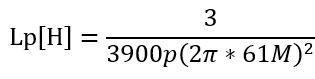
手順3:スナバ容量Csを用いて寄生インダクタンスLpを式(1)から求める
式(1)にそれぞれの値を代入した結果、寄生インダクタンスLp=5.24nHとなります。
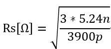
手順4:スナバ抵抗Rsを式(2)から求める
式(1)にそれぞれの値を代入した結果スナバ抵抗Rs=2Ωとなります。
これらの手順の結果スナバ回路の定数はRs=2Ω、Cs=3900pFが得られました。
妥当性の検証
図5のようにスナバ抵抗Rsを追加した回路を追加してシミュレーションをおこないます。
今回の回路では図6の波形のようにリンギングを大きく減少させることができ妥当な結果を得ることができました。
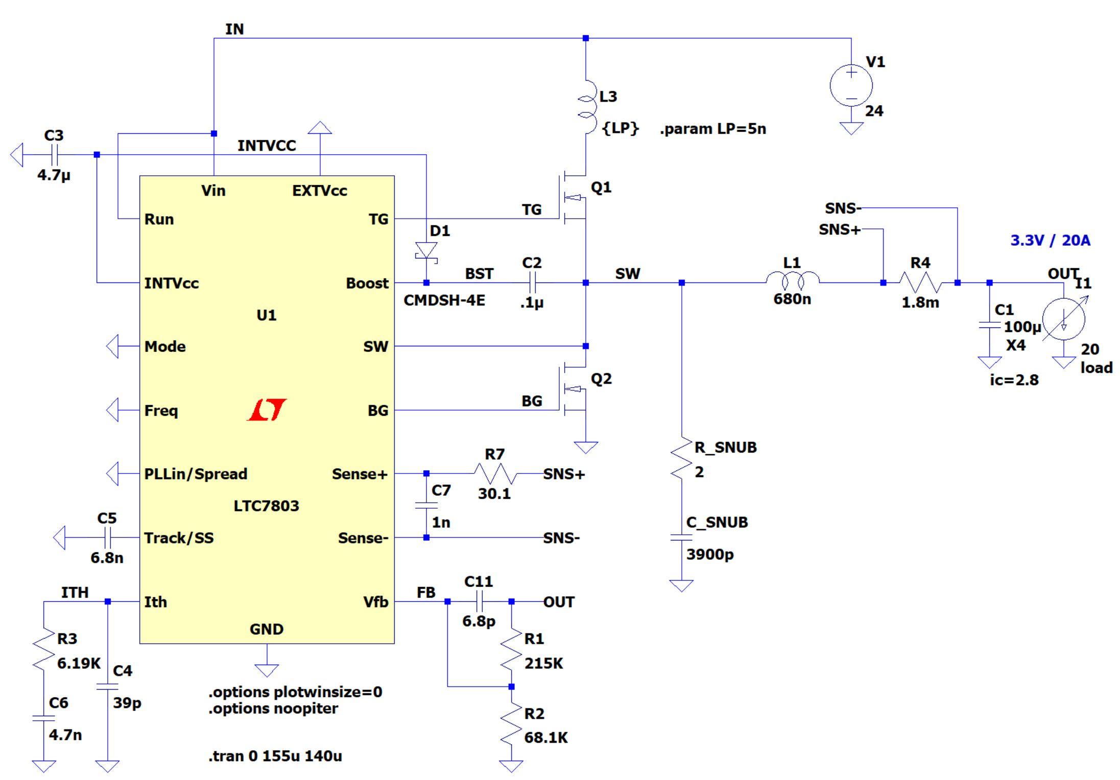
図5:スナバ定数検証回路
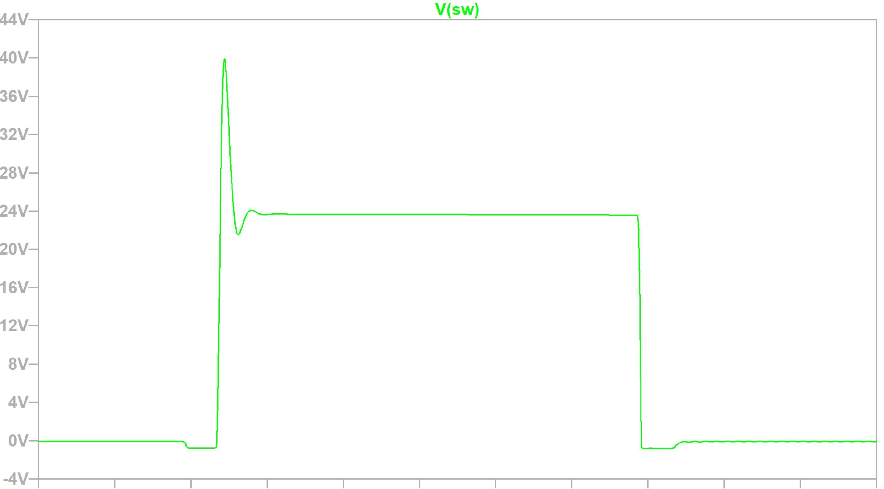
図6: 図5の回路におけるシミュレーション結果
スナバ抵抗Rsの消費電力
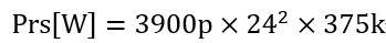
定数決定後にスナバ抵抗Rsの消費電力を(3)式より計算します。
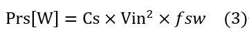
得られた結果を(3)式に代入します。
式(3)にそれぞれの値を代入した結果Prs=0.84Wとなります。
実際の回路ではスナバ抵抗Rsにはオーバーシュート/アンダーシュートがかかるため、この計算より大きい消費電力となるケースが想定されます。
LTspiceで各部品ごとの消費電力も確認することができるため、(3)式に加えてシミュレーションの結果を考慮してディレーティングを考慮した抵抗を選定してください。
おすすめ記事/資料はこちら
記事一覧:LTspiceを使ってみようシリーズ
LTspice FAQ : FAQ リスト
技術記事一覧 : 技術記事
メーカー紹介ページ : アナログ・デバイセズ社
おすすめセミナー/ワークショップはこちら
お問い合わせ
本記事に関してご質問がありましたら、以下よりお問い合わせください。
アナログ・デバイセズ メーカー情報Topへ
アナログ・デバイセズ メーカー情報Topに戻りたい方は以下をクリックしてください。