- Semiconductor BusinessHOME
- Products and Services of Macnica,Inc.
-
technical information

-
Events and Seminars
- Handling Manufacturer
- Support
- Inquiry
- Click here to purchase products
- Semiconductor business e-mail magazine registration
![]()
![]() Narrow down by specifying conditions
Narrow down by specifying conditions
現在2149件がヒットしています。check

This time, I will introduce how to use "Label Net" as a way to draw easy-to-read circuit diagrams.
If you are just starting LTspice, we recommend that you look at the "basics" from the list below.
Let's use LTspice series list is here
Also, if you would like to see a video on how to write a basic circuit and how to execute it, there is an on-demand seminar that does not require you to enter personal information, so please take a look if you are interested. Detailed information about the seminar is also provided to those who fill in the questionnaire.
LTspice On-Demand Seminar - Function check with RC circuit -
Which schematic is easier to see?
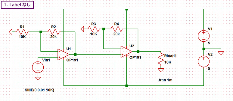
First of all, I have created two circuit diagrams for amplifiers using two operational amplifiers.
Which circuit diagram is easier to read?
Both have the same function, but the wiring in Figure 1 is straightforward.
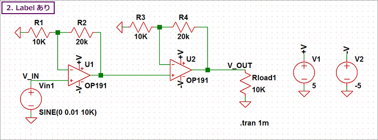
On the other hand, in Fig. 2, wiring was performed using Label Net.
In Figure 1, there are places where the power supply wiring and the signal wiring intersect.
On the other hand, Fig. 2 uses Label Net, so there are no wiring intersections.
For this reason, I think Figure 2 is easier to see.
How to use LabelNet
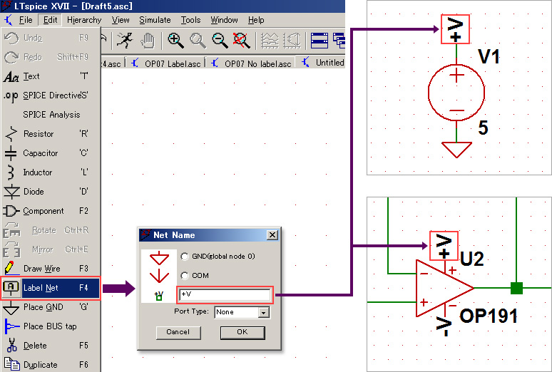
Select Label Net from the menu bar as shown in Fig. 3, give it an arbitrary name, and assign it to the wire (node). By assigning the same label name to the wiring, even if the wiring is far away, it is considered to be connected.
Therefore, using Label Net to separate the power supply and signal system makes it possible to draw an easy-to-read circuit diagram.
Name the measurement points with Label Net
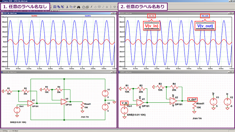
Let's run a simulation of the two types of op-amp circuits we created.
The measurement points are the signal source V1 and the output terminal of the operational amplifier (U2).
Looking at the waveform results, in Figure 4-2, we have assigned the arbitrary names "V_IN" and "V_OUT" to the wiring using Label Net, so it is easy to see which terminal the waveform result is for.
Figure 4-1 shows the node names n006 and n003 inside SPICE. Even if you look at the name of the waveform, it will be difficult to know which pin it is.
Therefore, it is recommended to use "Label Net" for the measurement point and give it an arbitrary name.
LTspice demo file verified this time
On a computer with LTspice installed, extract the zip file to the same folder, then run LTspice and the waveform display will begin automatically.
The amplifier circuit of the operational amplifier used this time
At the end
This time, we introduced how to create circuit diagrams using "Label Net" and check simulation waveform data.
First, download LTspice from the link below! Please try once.
Download LTspice here
We also hold regular LTspice seminars for beginners. You can learn the basic operation of LTspice, so please participate.
Click here for LTspice seminar information
Click here for recommended articles/materials
LTspice List of articles: Let's use LTspice series
LTspice FAQ: FAQ list
List of technical articles: technical articles
Manufacturer introduction page: Analog Devices, Inc.
LTspice seminar information
Inquiry
If you have any questions regarding this article, please contact us below.
Analog Devices Manufacturer Information Top
Analog Devices Manufacturer Information If you would like to return to the top page, please click below.