- Semiconductor BusinessHOME
- Products and Services of Macnica,Inc.
-
technical information

-
Events and Seminars
- Handling Manufacturer
- Support
- Inquiry
- Click here to purchase products
- Semiconductor business e-mail magazine registration
Texas Instruments' (TI) MSPM0 series microcontrollers feature a low-power Arm® Cortex®-M0+ core and a wide range of analog and communication peripherals, achieving high performance at a low price point.
The MSPM0 series is a microcontroller designed for a wide range of embedded applications, including home appliances, industrial equipment, building equipment, measuring instruments, and medical devices.
Equipped with a wealth of analog functions and various communication interfaces, it is also suitable for systems requiring motor control, power supply control, and CAN/LIN communication.
Features
- TImanufactures 300mm wafers using its own 65nm process at its own factory, ensuring a stable supply.
- Excellent expandability thanks to a wide range of analog peripherals.
- Ultra-low power consumption, operating at 1.0 μA in standby mode.
- The DSBGApackage (8-pin) achieves an extremely small size of 1.6mm x 0.85mm.
- Accelerate development with the provision of a wealth of software (driver libraries) and SysConfig (GUI tool).
portfolio
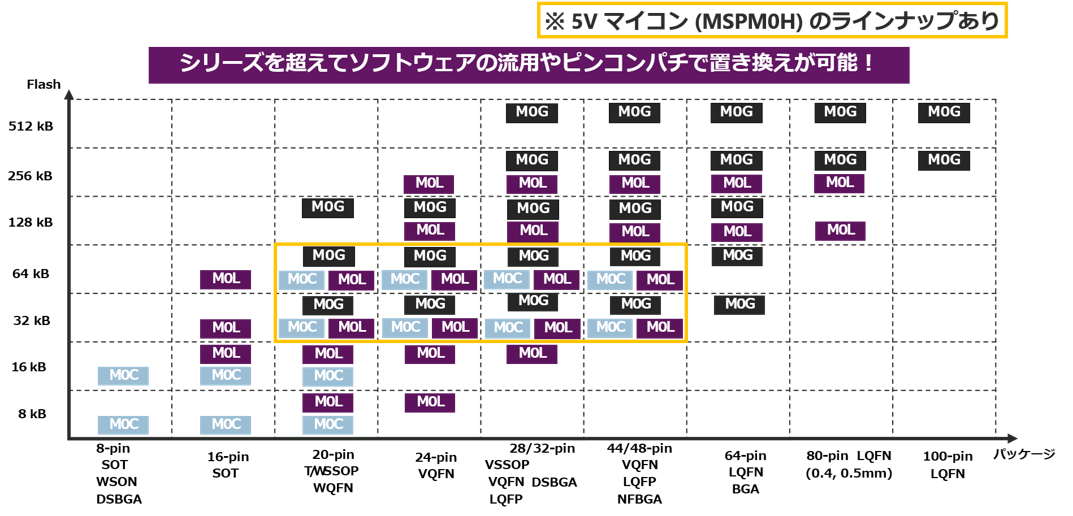
The MSPM0 series offers the following lineup, categorized by package and flash memory type:
The Arm® Cortex®-M0+ core is divided into series based on its operating frequency: the C series is 24MHz, the L series is 32MHz, and the G series is 80MHz.
Basically, all products operate on a 3.3V power supply (some pins are rated for 5V). However, only the MSPM0H series can be operated at 5V.
MSPM0C series
The C series offers packages as small as 1.6mm x 0.85mm, and is a series designed with miniaturization in mind.
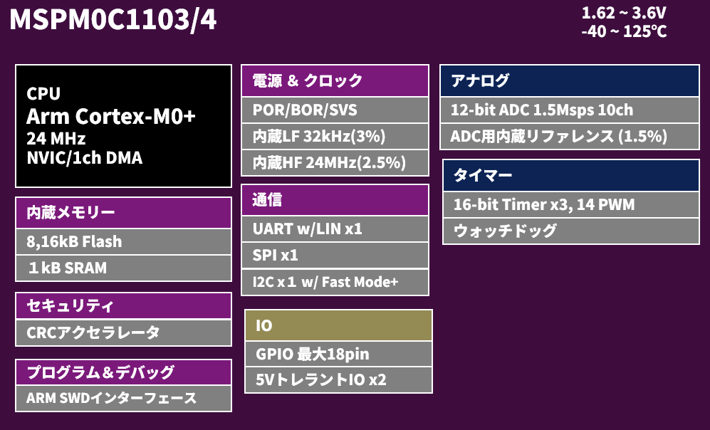
It features an ADC, DAC, timer (PWM), and RTC, and supports serial communication via UART, SPI, and I2C.
Functional block diagram
specification
|
Model number |
MSPM0C1103/4 |
MSPM0C1105/6 |
|
|
Operating frequency |
24 MHz |
32 MHz |
|
|
Internal clock accuracy(SYSOSC) |
-2 to +1.2 % |
-2.1 to +1.6 % |
|
|
Power supply voltage |
1.62 V - 3.6 V |
1.62 V - 3.6 V |
|
|
Operating temperature range |
-40 - 125 ℃ |
-40 - 125 ℃ |
|
|
Flash |
8 or 16 KB |
32 or 64 KB |
|
|
RAM |
1 KB |
8 KB |
|
|
GPIO(MAX) |
18 |
45 |
|
|
DMA |
1 |
1 |
|
|
analog |
ADC (MAX) |
12 bit -1 MSPS×10 ch |
12 bit -1.6 MSPS×27 ch |
|
12 bit DAC |
- |
- |
|
|
Reference8-bitDAC |
- |
1 (Output possible) |
|
|
High-speed comparator |
- |
1 |
|
|
General-purpose amplifier |
- |
- |
|
|
Zero Drift Amplifier |
- |
- |
|
|
Timer(MAX) |
16 bit×3 |
16 bit×5 |
|
|
Communication(MAX) |
I2C×1, SPI×1, UART×1 |
I2C×2, SPI×1, UART×3 |
|
|
Number of pins |
8 - 20 pin |
20 - 48 pin |
|
|
others |
- |
RTC |
|
MSPM0L series
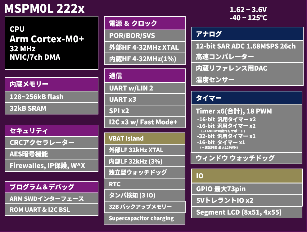
The L series consumes 1.0 μA in low-power mode and is a series designed with low power consumption in mind.
In terms of features, it includes an added operational amplifier and is the only model in the series to have a built-in LCD driver.
Functional block diagram
specification
|
Model number |
MSPM0L110x/130x |
MSPM0L111x |
MSPM0L112x/211x |
MSPM0L122x/222x |
|
|
Operating frequency |
32 MHz |
32 MHz |
32 MHz |
32 MHz |
|
|
Internal clock accuracy(SYSOSC) |
±1.2 % |
±1.2 % |
-2.1% ~ 1.6% |
±1.2 % |
|
|
Power supply voltage |
1.62 V - 3.6 V |
1.62 V - 3.6 V |
1.62 V - 3.6 V |
1.62 V - 3.6 V |
|
|
Operating temperature range |
-40 - 125 ℃ |
-40 - 125 ℃ |
-40 - 125 ℃ |
-40 - 125 ℃ |
|
|
Flash |
8 - 64 KB |
64 or 128 KB |
64 or 128 KB |
128 or 256 KB |
|
|
RAM |
2 - 4 KB |
16 KB |
12 KB |
32 KB |
|
|
GPIO(MAX) |
28 |
44 |
60 |
73 |
|
|
DMA |
3 |
3 |
3 |
7 |
|
|
analog |
ADC (MAX) |
12 bit -1.45 MSPS×10 ch |
12 bit -1.68 MSPS×13 ch |
12 bit -1.6 MSPS×25 ch |
12 bit -1.68 MSPS×26 ch |
|
12 bit DAC |
- |
- |
- |
- |
|
|
Reference8-bitDAC |
1(Output possible) * |
- |
1 |
1 |
|
|
High-speed comparator |
1 * |
- |
1 |
1 |
|
|
General-purpose amplifier |
1 |
- |
- |
- |
|
|
Zero Drift Amplifier |
2 * |
- |
- |
- |
|
|
Timer(MAX) |
16 bit×4 |
16 bit×4 |
16 bit×9 |
16 bit×5, 32 bit×1 |
|
|
Communication(MAX) |
I2C×2, SPI×1, UART×2 |
I2C×1, SPI×1, UART×2 |
I2C×2, SPI×2, UART×3 |
I2C×3, SPI×2, UART×5 |
|
|
Number of pins |
16 - 32 pin |
24 - 64 pin |
24 - 64 pin |
24 - 80 pin |
|
|
others |
- |
Dual BankFlash |
SegmentLCD (4x48, 8x44) * |
SegmentLCD (8x51, 4x55) |
|
* Some models may not support peripherals.
MSPM0G series
The G series enables high-speed processing with its computing accelerators and is a series designed with high performance in mind.
In terms of features, it includes a 12-bit DAC, CAN-FD, USB, and I2S, and is the only model in the series to have an accelerator (NPU) for Edge AI.
Functional block diagram
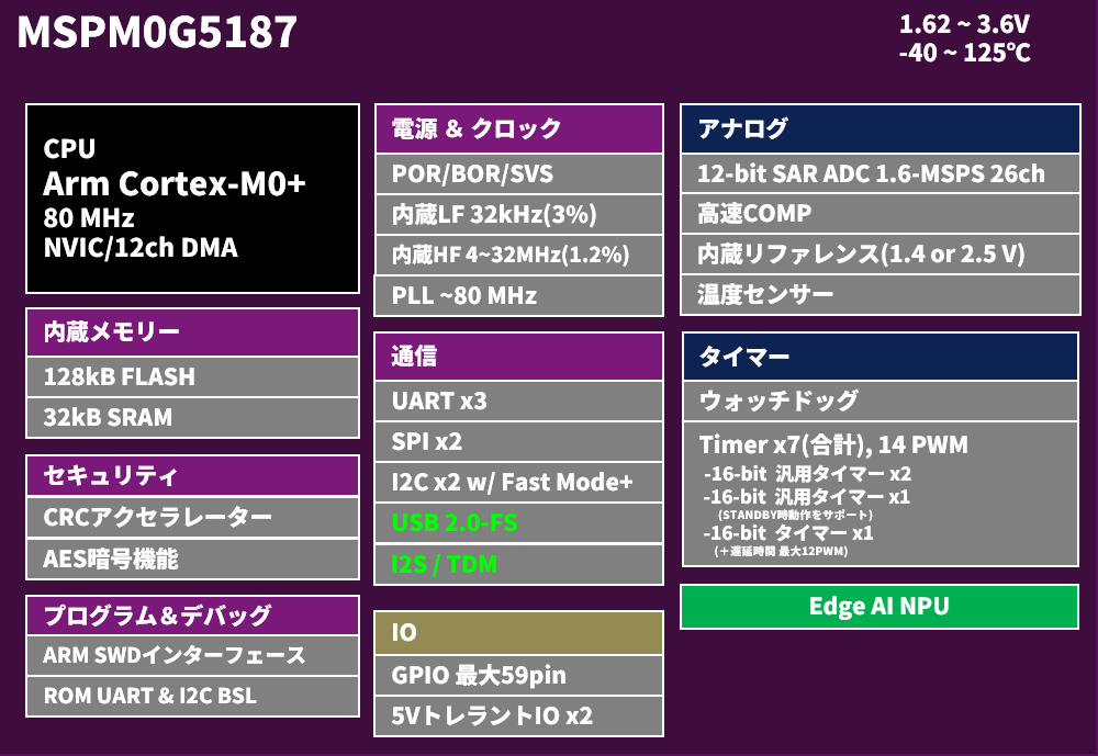
specification
|
Model number |
MSPM0G3x0x/1x0x |
MSPM0G351x/151x |
MSPM0G51xx |
|
|
Operating frequency |
80 MHz |
80 MHz |
80MHz |
|
|
Internal clock accuracy(SYSOSC) |
±1.2 % |
±1.0 % |
±1.2 % |
|
|
Power supply voltage |
1.62 V - 3.6 V |
1.62 V - 3.6 V |
1.62 V - 3.6 V |
|
|
Operating temperature range |
-40 - 125 ℃ |
-40 - 125 ℃ |
-40 - 125 ℃ |
|
|
Flash |
32 - 128 KB |
256 or 512 KB |
128 KB |
|
|
RAM |
16 or 32 KB |
128 KB |
32 KB |
|
|
GPIO(MAX) |
60 |
93 |
59 |
|
|
DMA |
7 |
12 |
- | |
|
analog |
ADC (MAX) |
12 bit -4 MSPS×17 ch |
12 bit -4 MSPS×14 ch |
12 bit -1.6 MSPS×14 ch |
|
12 bit DAC |
1 * |
1 |
- |
|
|
Reference8-bitDAC |
3(Up to 2ch output possible) * |
3 |
1 |
|
|
High-speed comparator |
3 * |
3 |
1 |
|
|
General-purpose amplifier |
1 |
- |
- |
|
|
Zero Drift Amplifier |
2 * |
- |
- |
|
|
Timer(MAX) |
16 bit×6, 32 bit×1 |
16 bit×8, 32 bit×1 |
16 bit×4 |
|
|
Communication(MAX) |
I2C×2, SPI×2, UART×4 |
I2C×3, SPI×3, UART×7 |
I2C×2, SPI×2, UART×3 |
|
|
Number of pins |
20 - 64 pin |
32 - 100 pin |
20 – 64pin |
|
|
others |
Computation accelerator |
Computation accelerator |
Computation accelerator
|
|
* Some models may not support peripherals.
評価ツール
Hardware evaluation tool
TI provides evaluation boards for the MSPM0 series. Additionally, a JTAG emulator compatible with the MSPM0 series is available.
software development kit
A software development kit (SDK) is provided by TI, and development can be done using Code Composer Studio, an integrated development environment (IDE) provided free of charge by TI.
Code Composer Studio also includes SysConfig, a system configuration tool, which allows for GUI-based configuration.
Macnica original content - MSPM0 series thorough explanation! ~
For those interested in the details and development methods of the MSPM0 series, we have prepared helpful resources.
This guide provides a clear and easy-to-understand explanation of the necessary environment for microcontroller development (Code Composer Studio and a JTAG emulator), as well as how to program and debug using them. Furthermore, it carefully illustrates peripheral functions that often stumble in programming, such as AD converters, amplifiers, and timer interrupts, from their basic functions to their practical use.
Please see below!
Contact Us
If you have any questions or concerns, please contact us using the form below.
the Company product representative will reply.