- Semiconductor BusinessHOME
- Products and Services of Macnica,Inc.
-
technical information

-
Events and Seminars
- Handling Manufacturer
- Support
- Inquiry
- Click here to purchase products
- Semiconductor business e-mail magazine registration
![]()
![]() Narrow down by specifying conditions
Narrow down by specifying conditions
現在2175件がヒットしています。check
Inductors and capacitors are essential components in electronic circuits. I will explain the basic role of its operation.
The contents of this time will be Part 1 "What is an inductor?" Inductors are large parts in power supply and filter circuits, so you want to make them small. However, it is necessary to be careful because if it is made smaller easily, it will cause heat generation.
If you want to see other articles, there is a summary page, so please take a look there.
Overview
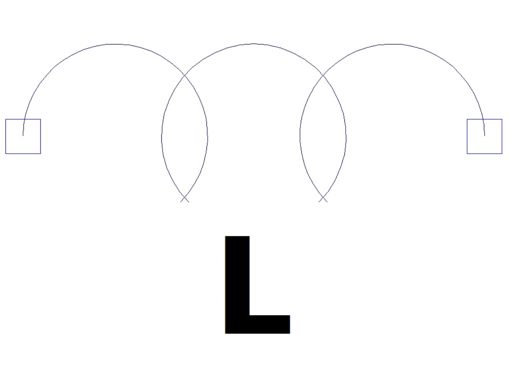
Along with resistors and capacitors, it is one of the representative passive components. Its circuit symbol is "L" and its unit is "H" (Henry).
Some engineers call them coils, chokes, or L, but you can basically think of them as synonyms.
The circuit symbol is shown like this.
Main applications are filter circuits, power supply circuits, high frequency circuits, etc.
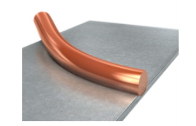
structure
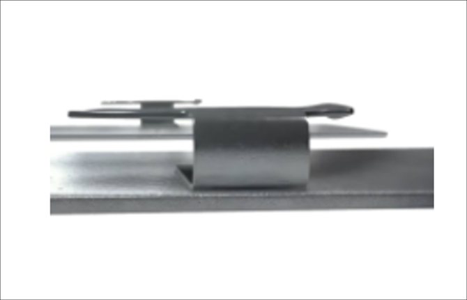
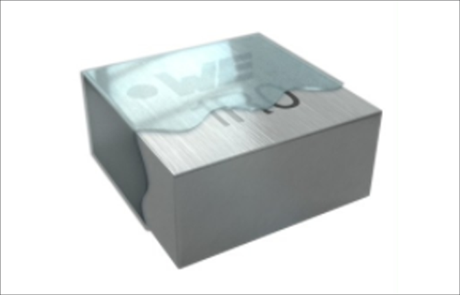
The basic structure is a structure in which a magnet wire is coiled around an iron core (core). The image below shows the flow of the manufacturing process of Wurth Electronics' WE-MAPI series.
You can also watch the video below.
Manufacturing process flow
Eliminating the lead frame ensures coplanarity, which is important for surface mounting
Improves reliability by connecting metals without soldering or welding
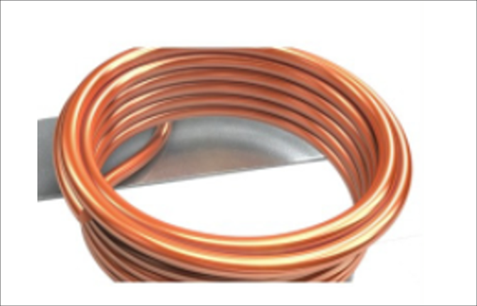
Maximize core properties for high current
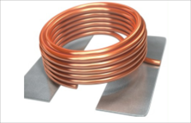
Increasing the coil diameter improves the inductor value
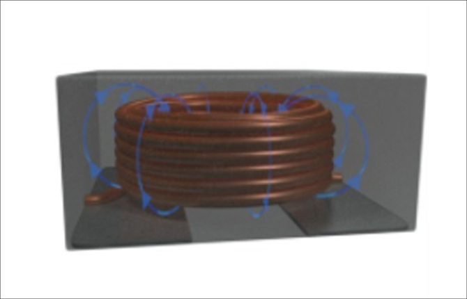
Improving EMI performance by wrapping the entire coil with metal powder
Protective coating increases robustness
Relationship between inductance, current and magnitude
To understand the relationship between inductance, current, and magnitude, we need to understand two things.
・Inductance can be obtained from the core performance (shape, material, etc.) and the square of the number of turns.
・The resistance value of a magnet wire depends on its cross-sectional area and length.
Each calculation formula is expressed as follows.
AL value: Value determined by core performance (magnetic permeability, cross-sectional area, magnetic path length).
N: number of turns
ρ: Resistivity
S: Cross-sectional area
ℓ: Length
For example, to make a 1 μH inductor 4 μH, we can see that the number of turns should be doubled. However, since the winding space is limited due to the shape of the iron core, in order to double the number of turns, it is necessary to change the diameter of the magnet wire to half by simple calculation, and the length will be doubled, so the resistance value is multiplied by 8.
A loss of P[W]=RI² occurs when the current flows through the resistor, so the heat generation of the inductor increases. You can see that increasing the inductance value and current rating increases the size.
If you would like to purchase from Macnica-Mouser, please click here
Ulto Electronics products are available for purchase at Macnica-Mouser (Macnica-Mouser), a mail order site for semiconductors and electronic components.
If you want to buy a product in a hurry, you can consider Macnica-Mouser.
Inquiry
If you have any questions about this product, please contact us using the form below.
Würth Elektronik Manufacturer Information Top
If you would like to return to the Würth Electronics Manufacturer Information top page, please click below.