- 半導体事業HOME
- マクニカの製品・サービス
-
技術情報

-
イベント・セミナー
- 取扱メーカー
- サポート
- お問い合わせ
- 製品購入はこちら
- 半導体事業のメルマガ登録
![]()
![]() 条件を指定して絞り込む
条件を指定して絞り込む
現在2183件がヒットしています。check
前回のチュートリアルでは、モジュールで構成する設計手法 は、信頼性が高く、仕様の違いに対応できる、高性能な電力供給ネットワーク (PDN)を、限られた時間で開発する場合に有効であることを示しました。また、後半ではスイッチング電源モジュールを用いてDC-DCシステムを開発するときに必要な、フィルターの設計方法 を解説しました。
第3回のチュートリアルでは、電力源と電源モジュールの相互接続に起因して、フィルター部品や配電線インピーダンスによって生じる安定性の問題を取り上げます。
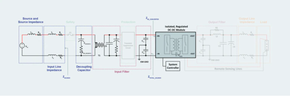
図1: DC-DCコンバーターモジュールを中心として完全な電源システムを設計するには、フィルター回路が必要です。
フィルターを付加することでシステムの安定性に問題が生じるため、電力源とコンバーターをデカップリングする対処が必要です。
安定性解析の原則
DC-DCコンバーターシステム全体の安定性を解析するためには、まず、電力源と負荷という2つのサブシステムに分けて考えます。ここで、「負荷」サブシステムは、DC-DCコンバーターそのものです。電力源のインピーダンス、入力ラインのインピーダンス、入力フィルターは電力源サブシステムの一部です。
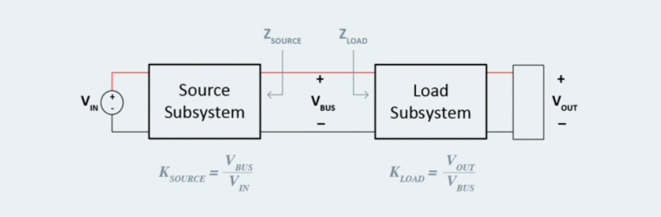
図2: 安定性を解析するために、相互作用する理想的な電力源サブシステムと負荷サブシステムに分けて、ブロック図で表します。
電力源サブシステムと負荷サブシステムは、それぞれ本質的に安定していると考えられます。しかし、この2つをVBUS で接続すると、様々な相互作用により発振が起こり、システムが不安定になる場合があります。
このタイプのシステムの安定性を解析する場合、入力フィルターや前段に設置される部品によって、DC-DCコンバーターから見た電力源のインピーダンスが、周波数に依存した有限な値になることに気を付ける必要があります。有限な出力インピーダンスを持つ電力源サブシステムにより、同様に有限の入力インピーダンスを持つ負荷サブシステムは給電されますが、このときのインピーダンス比は、システムの安定性を分析する上で鍵となる重要な要素です。ミドルブルック法の安定性判別基準にもありますが、負荷サブシステムの入力インピーダンスが電力源サブシステムの出力インピーダンスより大きい場合にのみ、システムは安定します。
このインピーダンスの比率は、システムのマイナーループゲインとして定義されます。すなわち、DC-DCコンバーター側を見た入力インピーダンスに対する、電力源サブシステム側を見た電力源インピーダンス(入力フィルタと、接続されたすべてのインピーダンスと、電力源そのものの出力インピーダンスを含む)です。
この関係に基づいて比率 (TMLG) を定義します。システムの安定性を確保するためには、電力源インピーダンスを負荷インピーダンスより小さくする必要があります。
この条件を外れると、回路のダンピングが不十分になり、システムが極めて不安定になる恐れがあります。実際には、電力源とDC-DCコンバーターの間に負性抵抗が形成されるため、システムが発振する可能性が生じますが、これはシステムの動作上、極めて大きな問題です。
コンバーターの入力部と電力源インピーダンスのデカップリング
発振によってシステムが不安定にならないように、電力源インピーダンスと負荷インピーダンスをデカップリングします。これは、DC-DCモジュールの入力側にデカップリングコンデンサーを配置することで効果的に実現できます。分かりやすくするために、図1では、電力源を簡略化して、テブナンの等価回路(理想的な電力源と個別のインピーダンスのブロック)で表しています。さらに、DC-DCコンバーターへつながる配線のインピーダンス(インダクタンスと抵抗で構成される)も、電力源サブシステムの一部とします。
DC-DCコンバーターと電力源の間のバスでシステムを区切り、電力源側を見た出力インピーダンスとDC-DCコンバータ側を見た入力インピーダンスを、明確にします。簡単にするために、DC-DCコンバーターの入力インピーダンスは抵抗文のみとし、すべての周波数で固定であると仮定します。安定性の解析が重要なのは、この低い周波数から高い周波数に移行する点です。インダクタンスの特性を持つ電力源サブシステムの出力インピーダンスが増大するためです。
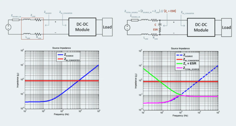
図3: ESRを持つ静電容量を挿入することで、高い周波数領域でも、電力源インピーダンスがDC-DCコンバーターの入力インピーダンスより低くなるため、システム全体の安定性が確保できます。
高い周波数領域で安定性を確保するためには、DC-DCコンバーターを接続する電力源インピーダンスを調整する必要があります。比較的容易な方法は、ダンピングの要素である。静電容量と等価直列抵抗 (ESR) を追加することです。
電力源の出力インピーダンスとDC-DCコンバーターの入力インピーダンスの間に挿入した容量性インピーダンス(緑の線)は、周波数の増加に伴って低下し、電力源のインダクタンス成分をバイパスします。したがって、DC-DCコンバーターが動作する低い周波数領域から高い周波数領域にわたり、電力源側の等価出力インピーダンスを低くすることができます。
入力フィルターとシステムの安定性
DCシステムに入力フィルターを付けると、電力源側の出力インピーダンスが変化し、システムの動作が不安定になることがあります。フィルター素子を追加することによって、ミドルブルック法の安定性判別基準を満たさない状態になると、システムの不安定な動作や発振が起こる場合があります。不安定なシステムでは、負荷の変動が振動を起こす原因となり、不必要な入力バス電圧の過渡変動が発生します。
DC-DC電圧調整機能のあるDC-DCコンバーターの入力インピーダンスを定義するときのシステムの動作条件は、入力電圧が最小で入力電力は最大とします。そうすると、前の例と同様にして、DC-DCコンバータの入力インピーダンスの抵抗分の近似値が得られます。DC-DCコンバーターの入力インピーダンスの抵抗分の近似値と、電力源側の出力インピーダンス(追加のフィルター素子を含む)を比較することで、システムの安定性が評価できます。
図4の解析例は、初期の入力フィルターの設計を示しており、電力源インピーダンスの共振ピークが10kHzと11kHzの間にあります。この共振ピークに起因して、電力源インピーダンスと負荷のインピーダンスの間で何かしらの相互作用が生じていることが分かります。これは、電力源に入力フィルターを組合わせた周波数応答に対するダンピング不足が原因です。この周波数領域では、電力源のインピーダンスが負荷のインピーダンスより大きくなるため、システムの動作が不安定になると予想できます。
しかし、適切にダンピングすることで、共振ピークを小さくすることができ、DC-DCコンバーターの入力インピーダンスと電力源の出力インピーダンスを適切にデカップリングすることができるため、ミドルブルック法の安定性判別基準を満たすことができます。フィルター回路を適切にダンピングすることで、このシステムは不要な発振や不安定性を回避することができ、良好なトータル性能が発揮できます。
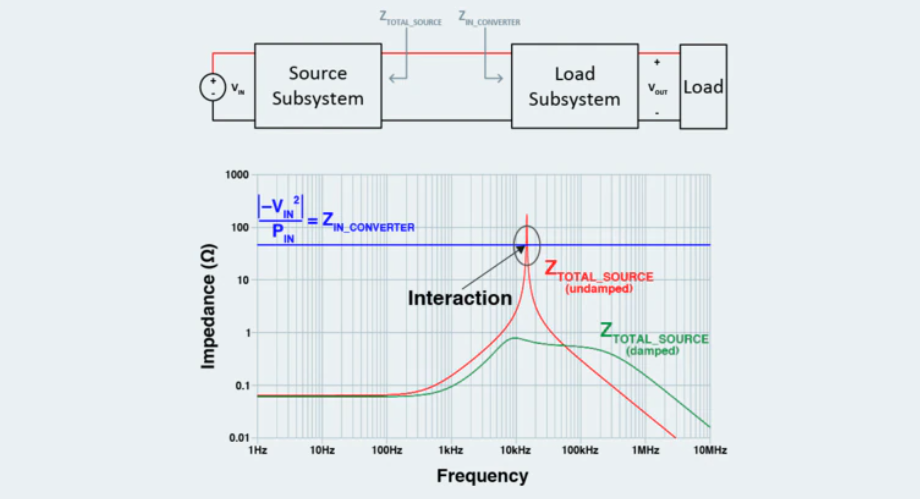
図4: システムに入力フィルターを付ける場合は、DC-DCコンバーターの入力インピーダンスの最悪値を想定してインピーダンス解析をおこない、ダンピングの調整をして、安定性を確保する必要があります。
基本的なシステム設計が完了すると、次の段階へ
この段階で、DC-DCシステムの設計はアプリケーションの要求を満たしました。アーキテクチャーとDC-DCモジュールが決定し、モジュールのノイズによる影響を軽減するために適切なフィルタを付加し、高い周波数領域の最悪条件を想定したシステム全体の安定性を確保しました。安定した効果的なシステムが確立できたので、次の設計段階では、システムを故障の原因になる過渡現象から保護し、周囲のシステムを含めて重大な障害から保護します。
次のチュートリアルでは、これについて検討します。