- Semiconductor BusinessHOME
- Products and Services of Macnica,Inc.
-
technical information

-
Events and Seminars
- Handling Manufacturer
- Support
- Inquiry
- Click here to purchase products
- Semiconductor business e-mail magazine registration
![]()
![]() Narrow down by specifying conditions
Narrow down by specifying conditions
現在2162件がヒットしています。check

Comparing "Voltage Controlled Oscillators" and "Digitally Controlled Oscillators"
What oscillators have you used in applications that require oscillator frequency tuning?
Perhaps you have been using voltage-controlled oscillators, so-called VCXOs (or VC-TCXOs).
In addition to this “other than VCXO”, there is also a “method of frequency tuning by digital input”.
In this article, we will introduce the SiTime DCXO (DC-TCXO) lineup in depth while explaining the advantages of using the expression "digitally controlled oscillator = DCXO".
Advantage 1 / Number of divisions can be deleted
"Digitally controlled oscillator = DCXO" does not require analog source for DA conversion or other voltage control on the system compared to VCXO.
It is possible to reduce the number of parts and cost.
Advantage 2 / Reduction of noise effect
It is also possible to eliminate the frequency shift caused by noise on the substrate of the voltage line.
The analog signals used to drive the voltage pins of the VCXO are very sensitive to noise.
May be susceptible to noise coupling.
Frequency control with digital inputs is performed through a digital interface such as IC andis therefore immune to analog noise coupling.
Advantage 3 / Wide pull range
This is especially true for “SiTime's MEMS-based DCXO,”
For digital control via a decimal point feedback divider,
It is possible to prepare a wider range than the pull range limited by the oscillator like the crystal product.
Actually touch SiTime's DC-TCXO "Digitally Controlled Oscillator mode"
Overview
SiTime's "Elite Platform™ Super-TCXO™ Series" is more than just a DCXO, it combines TCXO-level accuracy.
Both voltage control and digital control are available as frequency adjustment methods.
From here, the 'DCO mode' (Digitally Controlled Oscillator mode) of these ultra-precision TCXOs supporting digital input via the I2C interface.
I'm going to dig deep. DCO mode allows the output frequency to be continuously pulled within the specified pull range.
The pull range is configurable with one of 16 pull range options from ±6.25 ppm to ±3200 ppm.
DCO mode also allows customers to control the Output Enable (OE) state through writing to device registers. (need to select corresponding option)
Main product lineup
You can check it from here.
You can also inquire about the evaluation board from the following.
Digital control details
The DCXO powers up at the default operating frequency (and pull range) specified when ordering.
After powering up the IC, both the pull range and output frequency can be controlled by writing to the corresponding control registers through the digital interface.
The pull range is half the peak to peak deviation.
(e.g. 200ppm Peak to Peak is half that, ±100ppm)
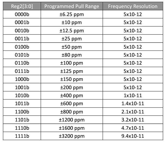
It is also determined by the value loaded into the Digital Pull Range Control register (Reg2[3:0]).
Sixteen pull range choices are recorded in this control register and range from ±6.25 ppm to ±3200 ppm.
order code
Below is the corresponding programming code (which can be specified in the model number when ordering) and program values for frequency resolution and pull range.
Frequency pull procedure
1. Calculate the ratio of the target pull value (targetPull) to the pull range (pullRange) (Formula 1)
2. Multiply the fraction of the target pull value by the full half scale word value and round to the nearest integer (Formula 2)
3. Convert the above result to 2's complement binary (pullControlWordBin)
4. Read the Reg1 value from the device (because it may contain control bits for other settings)
5. Form the contents of the registers for writing
- a. Reg0[16:0] – pullControlWordBin[15:0] (LSW)
- b. Reg1[9:0] – pullControlWordBin[25:16] (MSW)
- c. Reg1[15:10] – Do not change
6. Write the registers in the following sequence
- a. Reg0
- b. Reg1

Formula 1

Formula 2
At the end
What did you think.
This time, we focused on DCXO (Digitally Controlled Oscillator) and introduced SiTime products.
Please feel free to contact us if you have any questions during the design process.