- Semiconductor BusinessHOME
- Products and Services of Macnica,Inc.
-
technical information

-
Events and Seminars
- Handling Manufacturer
- Support
- Inquiry
- Click here to purchase products
- Semiconductor business e-mail magazine registration
![]()
![]() Narrow down by specifying conditions
Narrow down by specifying conditions
現在2164件がヒットしています。check

Introduction
In this article, we will introduce the actual operation check of Renesas' FGIC (Li-ion Battery Fuel Gauge IC) RAJ240100. This time, we carried out the following:
・Introduction of REL 's FGIC Starter kit and operation check of the introductory GUI"RSB TOOL"
・Calibration is performed using a stabilized power supply, electronic load, and ladder resistor.
- Connect an actual Li-ion battery and check the discharge and charge operations on the GUI
Please also check the related pages below.
・ Basic knowledge of how to predict the remaining charge of a lithium-ion battery (Li-ion battery)
・ Renesas Battery Level Management IC Products
Introducing the RAJ240100 Starter kit
Renesas offers the following evaluation kits:
The kit includes device files, sample code, monitor tools, USB drivers and documentation.
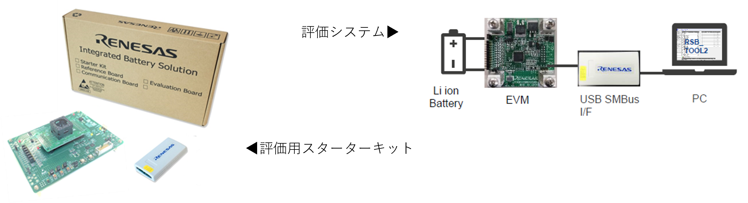
The board I'll be using this time is as follows:
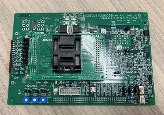
3 ~ 10 Corresponding to the cell, RAJ240100 Check the operation.
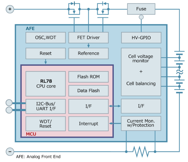
RAJ240100 The AK4110 is capable of low power consumption operation and is based on Renesas' RL78 CPU Core and analog and digital circuits 1 This product is built into the package and performs battery management functions such as measuring the battery voltage, current, and temperature, estimating remaining charge, and protecting against overcurrent, voltage, and temperature.
Connecting the Starter Kit
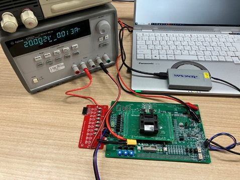
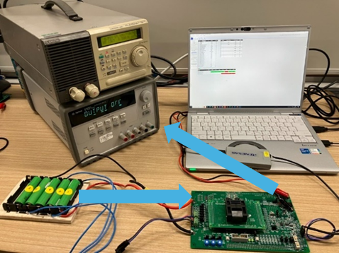
The configuration confirmed this time is as follows:
Instead of a battery, it is equipped with a stabilized power supply and a voltage dividing resistor ladder (red board), a board equipped with RAJ240100, a USB-SMBus conversion interface, a PC, a stabilized power supply, and an electronic load.
Also, sample tool software for monitoring the FGIC is installed on the PC.
This time, we'll assume 4V per cell, and a total of 20V for five cells in series, so we'll apply 20V from a DC voltage source and divide it by 5 via a resistor ladder board, inputting five voltages to the board: 20V, 16V, 12V, 8V, and 4V. After confirming that the intended voltages have been input to the board, press the board's power button to power it on.
Including checking whether the board and sample tools are working properly.
Let's check the voltage values input to the board at this time using the sample tool. The results are as follows:
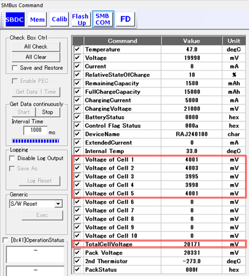
Cell 1, 2, 3, 4, and 5 are displayed as 4001mV, 4003mV, 3995mV, 3998mV, and 4001mV, respectively. The actual voltages input were 20V, 16V, 12V, 8V, and 4V, but the voltage values per cell are displayed, as shown above. The total cell voltage was 20171mV, which was also roughly correct.
Calibration
If you are unable to confirm the intended voltage here, it may be possible to improve the situation by applying correction through calibration.
This time we will try to perform two-point correction using the tool.
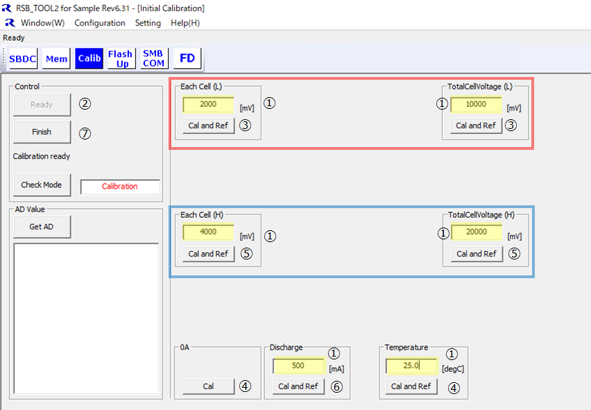
As shown above, on the calibration screen of the sample tool, set the voltage (single cell / whole cell), current (without / with load current), and temperature between two points (red frame / blue frame), and then enter the specified voltage / current at the specified temperature to perform calibration.
In this example, the steps are as follows:
① Enter the value of the yellow marker on the sample tool.
1 Start voltage (1 cell 2,000mV, the whole cell 10,000mV), 2 Start voltage (1 cell 4,000mV, the whole cell 20,000mV), load current 500mA, temperature 25. 0 Enter a value in degrees Celsius
② Click the Ready button
③Set the DC voltage source value to 10V, input the voltage to the board, and click the two buttons in the red frame.
④Click the 0A and Temperature buttons respectively.
⑤Set the DC voltage source value to 20V, input the voltage to the board, and click the two buttons in the blue frame.
⑥Set the load current source to 500mA, drain the current from the terminal on the board, and click the Discharge button.
⑦ Click Finish.
This completes the calibration procedure.
Simulated charge/discharge test
An electronic load was used during the calibration procedure described above.
This can be used to perform simulated battery discharge tests, and a simulated charging test can be performed using the charge control board.
We will charge and discharge the battery and check its operation on the tool.
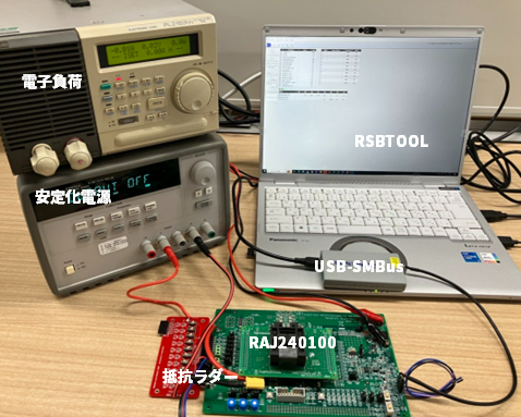
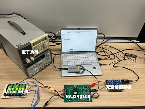
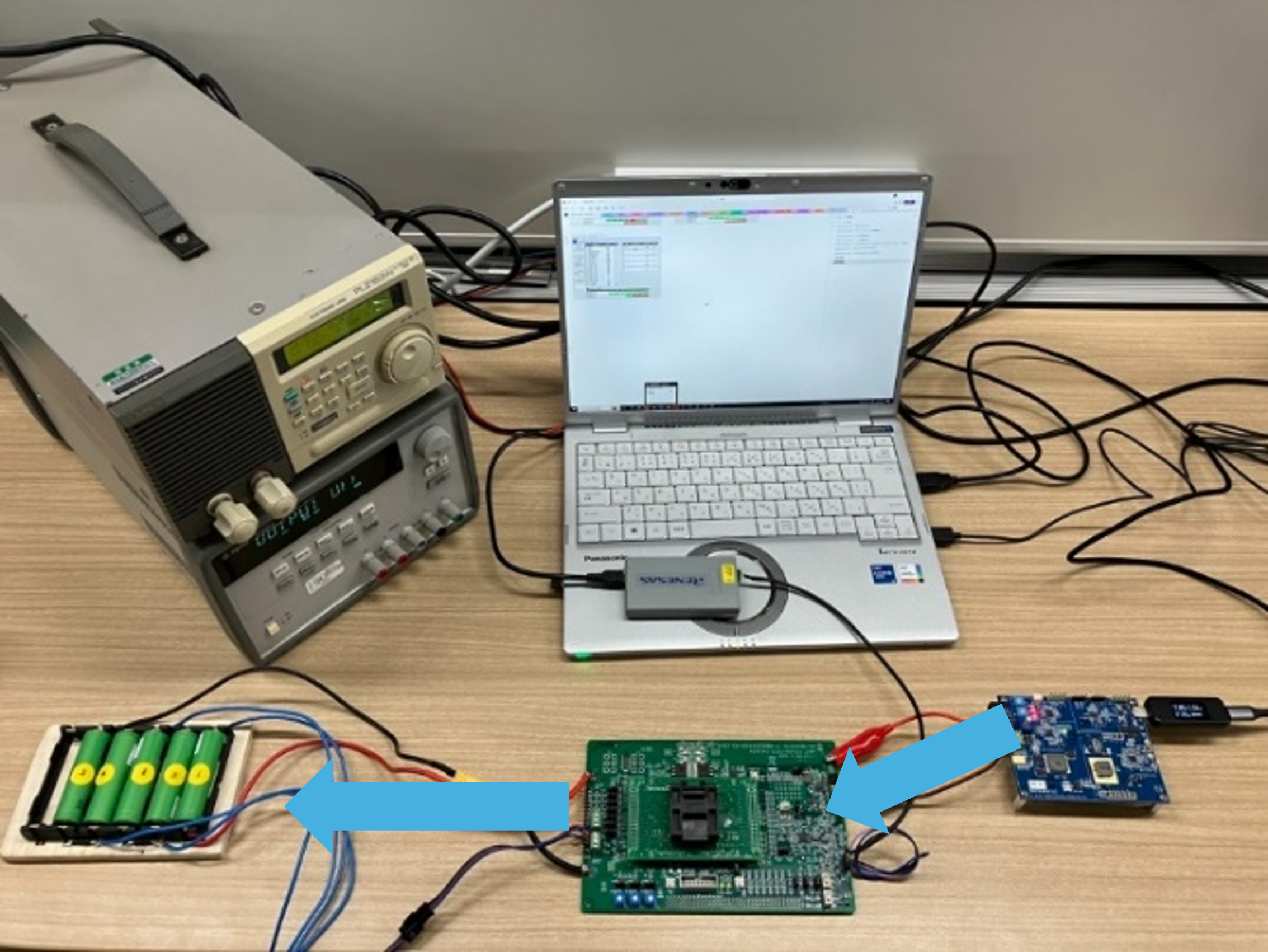
・Preparing for the test
As shown in the photo below, we prepared an electronic load, 5 Li-ion batteries, and a board for evaluating the charging operation.
Connect an actual battery and check the discharge and charging operations on the tool.
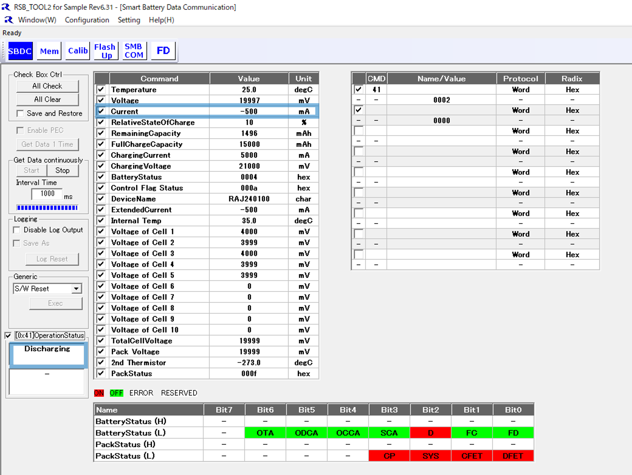
・Discharge operation check
Connect a battery and use an electronic load to draw current.
You can confirm that the status is "DISCHARGE" on the tool.
You can also read the 500mA being discharged from the tool.
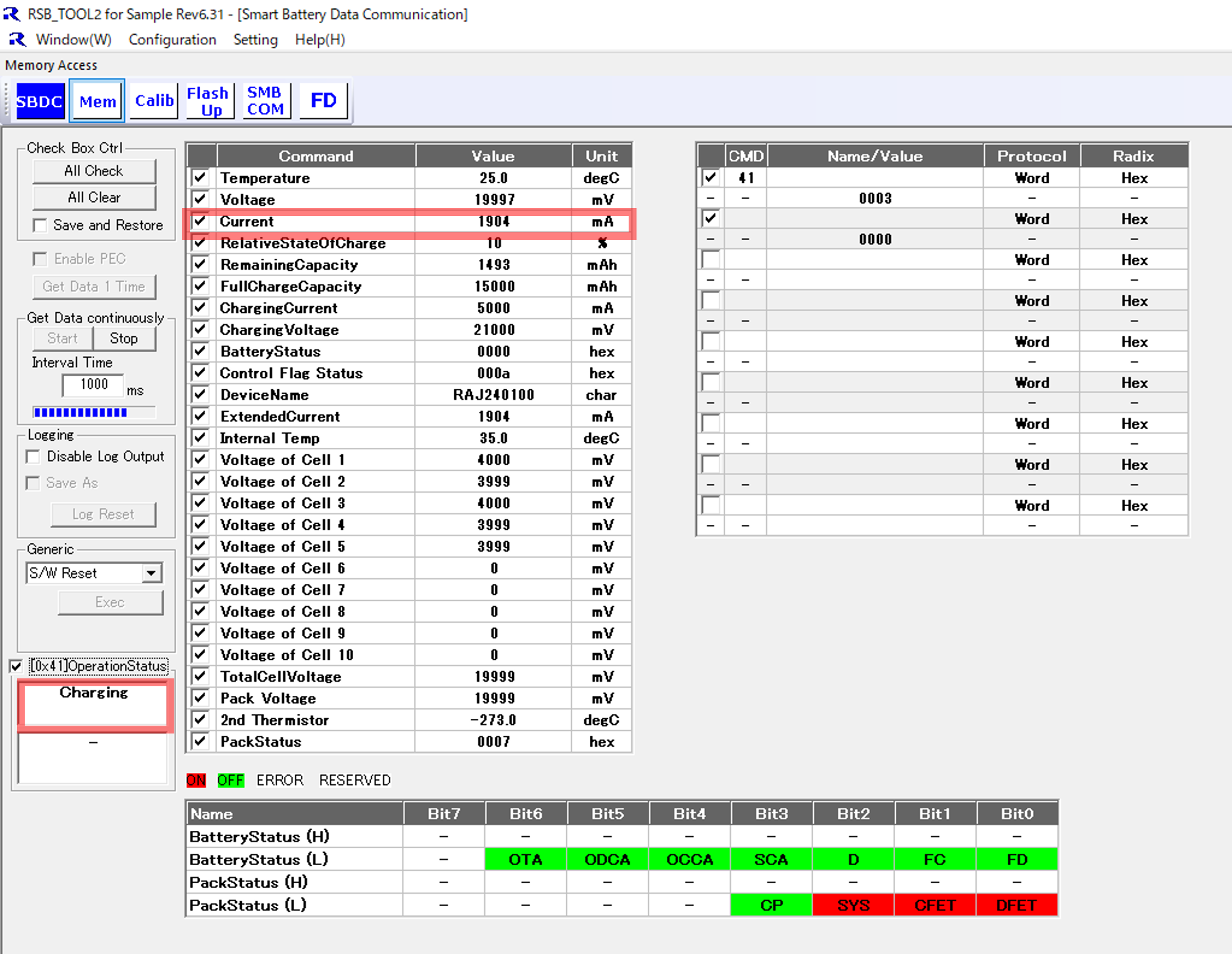
・Charging operation check
Connect the battery and perform charging from the charging evaluation board.
While charging, you can see that the sample tool is showing "CHARGE".
In addition, the actual current being charged to the battery was read as 1904mA.
Summary
This time, we used a Renesas FGIC evaluation board to easily check the calibration and the charging and discharging operation of a Li-ion battery.
Although you will need equipment such as a stabilized power supply, it is relatively easy to check how it works, so it is recommended if you would like to try it out first.
Click here to enquire about the starter kit