- Semiconductor BusinessHOME
- Products and Services of Macnica,Inc.
-
technical information

-
Events and Seminars
- Handling Manufacturer
- Support
- Inquiry
- Click here to purchase products
- Semiconductor business e-mail magazine registration
![]()
![]() Narrow down by specifying conditions
Narrow down by specifying conditions
現在2186件がヒットしています。check

Phase Noise
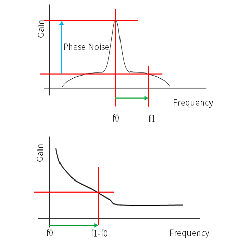
If you look at the waveform of an oscillator with a Spectrum Analyzer, you may have seen a waveform like the one on the right.
Phase Noise indicates how much noise power exists at the time when the frequency f0 (Carrier Frequency) of the oscillator is the center and the frequency is shifted from f0.
In the figure on the right, it corresponds to the gain difference between the noise power at a frequency apart from f0 and f1 and the peak value of f0.
The lower right figure is a graph showing Phase Noise, and the point showing Phase Noise at the frequency difference between f0 and f1 in the upper right is the intersection of the red line.
Phase noise is generally caused by factors such as source frequency fluctuation, temperature fluctuation, and circuit configuration.
If the Q value is large, the phase noise can also be reduced, but when multiplying with a PLL, etc., the higher the multiplication number, the smaller the bandwidth cannot be taken, so the phase noise will be affected. easier.
Also, Phase Noise uses dBc as the unit. The c in dBc means carrier frequency power, and means the ratio to noise power in 1Hz units.
Inquiry
To Microchip manufacturer information Top
If you want to return to Microchip manufacturer information top page, please click below.