- Semiconductor BusinessHOME
- Products and Services of Macnica,Inc.
-
technical information

-
Events and Seminars
- Handling Manufacturer
- Support
- Inquiry
- Click here to purchase products
- Semiconductor business e-mail magazine registration
![]()
![]() Narrow down by specifying conditions
Narrow down by specifying conditions
現在2161件がヒットしています。check
In today's society, where various "things" are connected to the Internet and exchange information, countless amounts of audio, video, email, and other data are flying around within the internetwork.
In this situation, various rules exist to ensure that packets are not dropped between the sending and receiving devices. This time, we will talk about the transmission interval between packets.
How is the frame-to-frame transmission interval determined?
Frame configuration of Ethernet
There are two frame formats: "DIX Ethernet (Ethernet II) Frame" and "IEEE802.3 Frame".
Currently, the most commonly used frame is the "DIX Ethernet (Ethernet II) Frame", and when referring to Ethernet Frame, it is usually the "DIX Ethernet (Ethernet II) Frame".
The difference between each frame is that "SFD" is added after the preamble and "EtherType" is "Size/EtherType", but most network devices can recognize either format, so there is no problem if they are mixed together.
Various information is stored in one Ethernet Frame according to the rules. The Ethernet Frame that flows over the LAN cable is as shown in the figure below, and the actual data is the destination MAC address.
It refers to the length from the beginning to the end of the FCS. The value can vary from 64 bytes to 1518 bytes, and the size of an Ethernet Frame is expressed in "number of bytes".
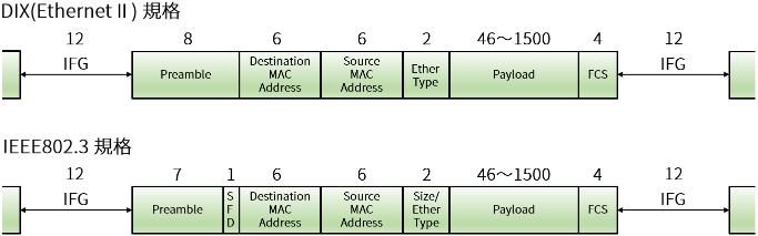
In addition, there are Preamble, SFD, and IFG, which are states in which no data is being sent.
- Preamble
In order to notify the receiver of the Ethernet Frame that "data is coming!" and give the timing for synchronization, the Ethernet Frame is
It is a 56Bit (7octet) Bit string of "101010...1010" added to the beginning.
- SFD(Start Frame Delimiter)
"01010111" is added to indicate the end of the preamble, which is the first field of the Ethernet Frame, and the beginning of the Ethernet Frame.
Bit string of 8Bit (1octet).
- IFG(Interframe Gap)
This is the interval between sending one Ethernet frame and the next. There is a minimum value, which is 12 bytes (96 bits).
The specific times for each communication speed are as follows:
10Mbps Ethernet 9.6 μsec
100Mbps Ethernet 0.96 μsec
1Gbps Ethernet 96ns
10Gbps Ethernet 9.6 nsec
Why IFG is necessary 1 ~ Frame Recovery Time ~
Models with power-saving features are available at low prices for recent network equipment.
To conserve power, a low power consumption mode (Sleep Mode) is implemented by limiting the power supply to unused LAN ports or when no signal is being received.
To return to normal communication from this state, the Ethernet frame receiver uses the IFG to recover the clock and prepare to receive the frame.
Also, when Ethernet frames are sent one after the other, the receiving side needs a "recovery time" to prepare to accept the next frame.
The IFG allows time for the receiver to prepare to accept the frame.

Why IFG is necessary 2 - Ethernet communication is asynchronous communication -
Unlike SONET/SDH, Ethernet communication is an asynchronous communication standard that does not synchronize the clock timing between the data sender and receiver.
In asynchronous communication, the data sender and receiver operate on their own clocks, resulting in clock deviation (clock error).
IEEE802.3u Fast Ethernet allows an error of up to ±100ppm at a 125MHz clock, resulting in an error of up to ±200ppm between adjacent devices.
The IFG is used to make adjustments so that the receiving device can receive the data correctly even when this clock deviation exists.
Microchip Ethernet related product information
Click below for information on Microchip's Ethernet related products.
Inquiry
If you have any questions regarding this article, please contact us below.
To Microchip manufacturer information Top
If you want to return to Microchip manufacturer information top page, please click below.