![]()
![]() Narrow down by specifying conditions
Narrow down by specifying conditions
現在1888件がヒットしています。check

Hello! I'm Ryosu, a new engineer on the Lattice team.
Last time, we decided on the concept and functional specifications for new module production.
This time, I would like to acquire a license, use the tool, and check the operation of the evaluation board!
For those of you who are visiting this blog for the first time, let me give you a brief overview of this blog.
In this blog, I will introduce the process of making a module that controls a temperature sensor, a 7-segment LED, and Silicon Labs' BGX with an FPGA.
(If you're interested, I'll attach links to other episodes below, so please take a look!)
License acquisition and tool installation
First of all, I would like to acquire a license and install tools as before.
Obtaining a license
The tool design to use is Radiant. After creating a Lattice account, you will be directed to the Lattice Radiant page.
Select Node-Locked License from the License section in the middle of the page.
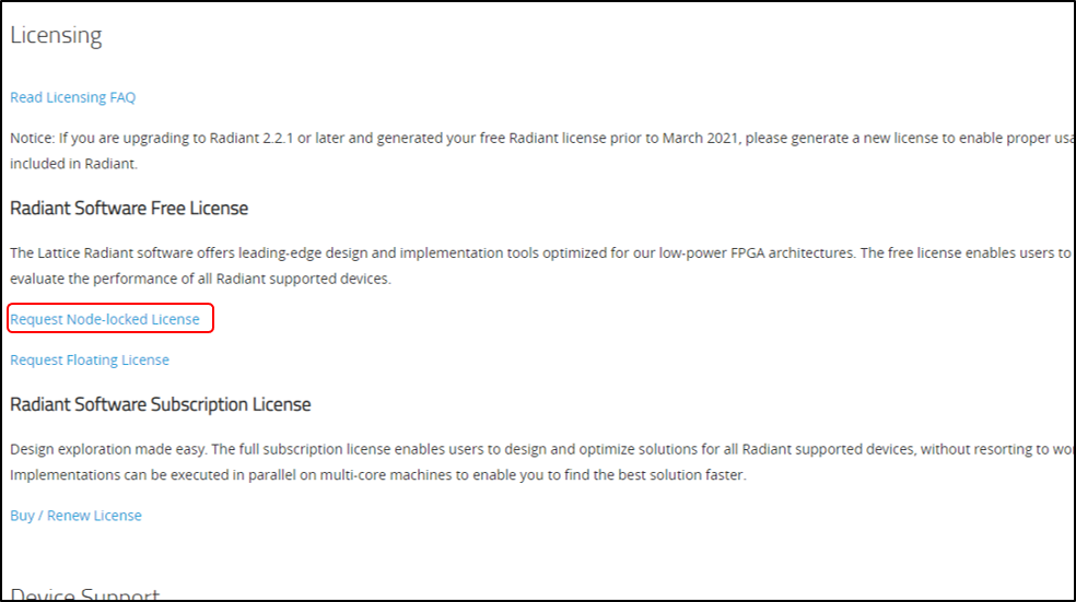
After entering the required information on the next page, press "Generate License" at the bottom of the page to acquire the license.
After confirming that you have received the license by email, you are done.
Tool installation and license storage
After obtaining the license, install the tool and store the license.
Install the latest version of the tool for your PC from Lattice's Radiant page. (installed with default settings)
After the installation is complete, store the license.
Store the license.dat emailed earlier under C:\lscc\radiant\3.1\license.
After storing, move to Edit Windows Environment Variables. Check if there is a path where the license is stored in the LM_LICENSE_FILE field.
If not, let me add it.
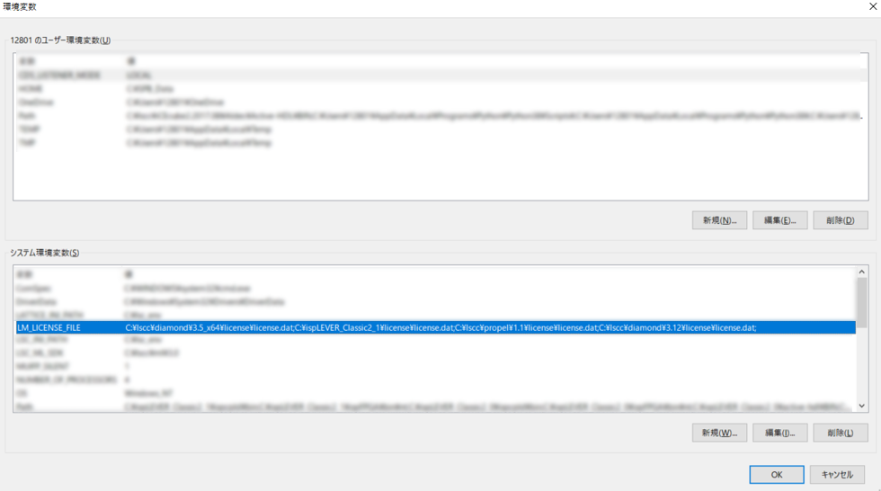
After checking the environment variables, start Radiant and it will be completed if it starts up without any errors.
NEXUS device evaluation board operation check
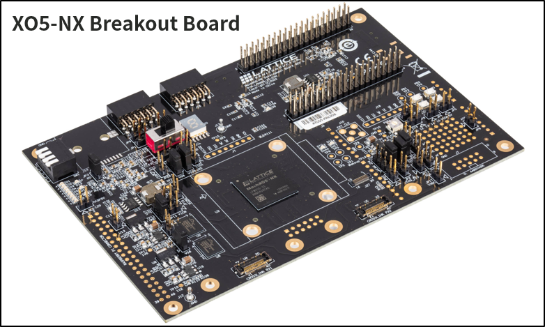
About the XO5-NX Evaluation Board
The device used this time is the XO5-NX, which is the only FPGA in the NEXUS series that has a built-in Flash.
The capacity is 25K LUTs, which is overspec, but I would like to use this evaluation board for the purpose of studying the new series of devices.
Evaluation board operation check
I would like to check the operation of the evaluation board. Since this is my first time using Radiant, I would like to confirm how to use the tools.
The design used this time is a module that lights up the LED on the evaluation board.
Compile this design, write it, and check if it can be evaluated on the actual machine.
The RTL block diagram is shown below.
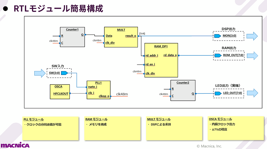
First, double-click ".rdf" directly under Sample in the file to load the project. Then compile and generate a programming data file.
Start Radiant Programmer and write to FPGA on the evaluation board.
After turning on the evaluation board and writing, the LED lighting on the evaluation board changed!
Sounds like no problem!
This design is the design used in the Radiant Archive Seminar. I've put a link at the bottom of the page, so if you're interested, check it out!
This time, we acquired the license, installed the tool, and confirmed the operation of the evaluation board.
As an impression, I thought it would take some time to get used to the design tool!
The functionality is the same, but the GUI is slightly different, and it took me a while to get used to it.
However, if you have touched Lattice's tools once, it doesn't seem to be a problem!
Next time, I would like to check the operation of BGX. See ya!
About the Lattice FPGA Getting Started Blog
Throughout the article, we are making a module that displays the temperature (SPI communication) acquired by the temperature sensor on a 7-segment LED display (GPIO) and a smartphone!
Also, in order to display it on a smartphone, we use Silicon Labs' BGX for wireless communication!
If you are interested in "What is this newcomer making?"
I would be happy if you could check the module production process and the whole picture from the page below!

*Currently under construction