- Semiconductor BusinessHOME
- Products and Services of Macnica,Inc.
-
technical information

-
Events and Seminars
- Handling Manufacturer
- Support
- Inquiry
- Click here to purchase products
- Semiconductor business e-mail magazine registration


 Narrow down by specifying conditions
現在2240件がヒットしています。check


It's Poki.
I decided to add JTAG_UART to the "Qsys design that gave Nios II only the function to blink the LED (so-called L blinking)" that Poki created before.
By adding JTAG_UART, you can output characters and numbers from FPGA to PC via JTAG.
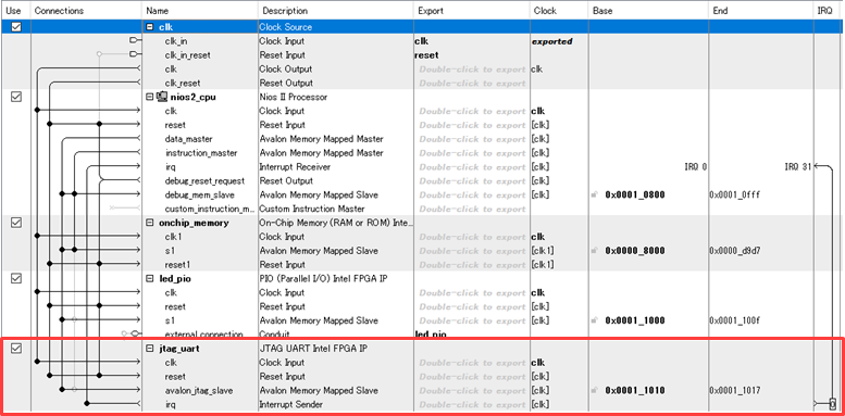
I re-Generated HDL Qsys and changed the hardware design.
After that, add alt_putsr to make the program output characters with JTAG_UART.
alt_putstr("Start!!\n");
However, when I build the above program, an error is output.
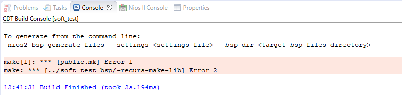
I found the cause of the error.
"The sopcinfo file was updated because I regenerated Qsys!"
Since SBT creates a BSP (Board Support Package) based on the sopcinfo file,
If the sopcinfo file is updated, the BSP and the program will become inconsistent.
* The sopcinfo file serves to pass the Qsys system configuration to the software development environment Nios II Software Build Tools for Eclipse ( SBT ).
"The inconsistency means that using the updated sopcinfo file,
Will I have to rebuild the software project again?
Since it is necessary to set BSP again, it is a little troublesome. ”
However! It didn't need to!
There was a way to use a software project that was already made!
What should i do?
Update existing BSPs when sopcinfo is updated to reflect Qsys design changes and
You can use your existing software projects!
Just right click on the BSP folder and select Nios II → Generate BSP.
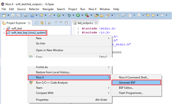
By clicking Generate BSP you can regenerate the BSP with the changes in the sopcinfo file.
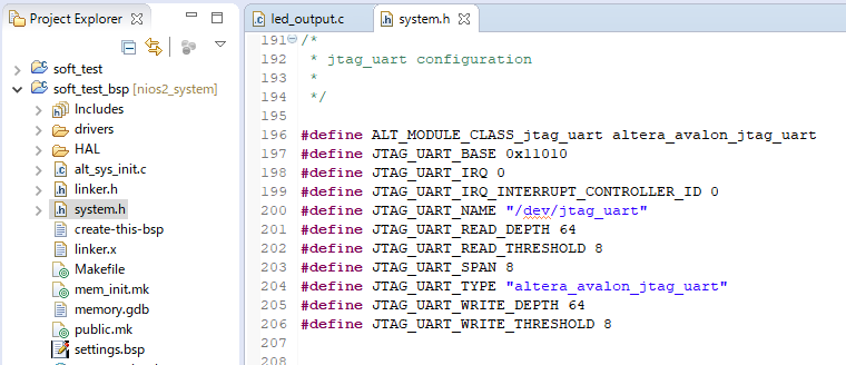
Let's check the system.h file to see if the changes were reflected correctly.
The header file called system.h in the BSP folder is
This is a macro definition file such as peripheral address values generated based on the sopcinfo file.
Looking at the contents, you can see that jtag_uart, which was not there before, has been added.
Also, if the program needs to be changed, such as adding a peripheral with Qsys and writing a new process like this time,
The data stored in the on-chip RAM will also change.
After that, as I introduced last time, do a full compile after mem_init_generate.
(Please refer to this content.)
After compiling, you will have a sof file with updated initial values for on-chip RAM.
Write this sof file, launch the console with nios2-terminal from Nios II Command Shell, and take a look...
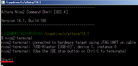
You can see that Start! is being output by the part of the program we wrote earlier.
Now you can change Qsys without recreating the software project.
You can start the software after one configuration!
At the end
This is about the MAX 10 Evaluation Kit used in this work.
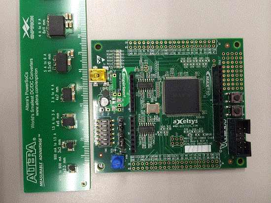
The MAX series didn't have a RAM block until now, so Nios II couldn't be installed.
However, since MAX 10 is equipped with RAM blocks, Nios II can be installed, and it has built-in Flash Memory,
No external Configuration ROM required!
It even has an ADC function!
This MAX 10 is lined up as an FPGA with built-in Flash Memory.
There is also a power supply with a built-in inductor called Enpirion, which is highly efficient and has a small mounting area!
Surprisingly, this is also a product of Altera!
As you can see from the ruler sample I was measuring earlier, it's very small.
Enpirion's small size as recommended power supply for FPGA makes it a perfect solution for board area reduction!
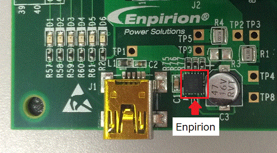
Isn't it good to try Nios II with this MAX 10 Evaluation Kit?
I would like to use this board to the fullest!