- Semiconductor BusinessHOME
- Products and Services of Macnica,Inc.
-
technical information

-
Events and Seminars
- Handling Manufacturer
- Support
- Inquiry
- Click here to purchase products
- Semiconductor business e-mail magazine registration
![]()
![]() Narrow down by specifying conditions
Narrow down by specifying conditions
現在2191件がヒットしています。check


Hello, I'm Hachi and I'm currently studying Altera® FPGAs.
In this article, we will study the configuration sequence in AS mode for Cyclone® IV devices.
As described in "Configuration Time", EPCS and Cyclone IV are connected as shown in the figure below.
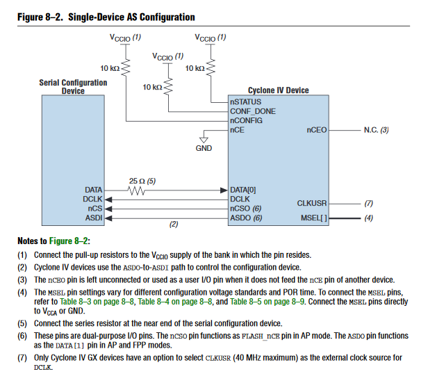
What does each signal mean?
I have summarized them in a table.
|
Cyclone IV pin names |
Overview |
| nCONFIG | Configuration control pin |
| nSTATUS | Configuration status pin |
| nCE | Chip enable pin |
| DATA[0] | Configuration data pin |
| DCLK | Configuration clock input/output pin |
| nCSOs | Chip enable output pin |
| ASDO | Configuration control pin |
As noted in Initialization Time, configuration data is typically loaded into the Cyclone IV from the EPCS after powering up the board.
Based on my own experience, I came up with the following three patterns for possible cases of the configuration sequence.
◆ Supplying power to the board
◆ Run configuration again
◆ Execute reconfiguration when a configuration error occurs
The movement of each pin during configuration is shown in the table below.
|
Signal name |
attribute |
value |
explanation |
| nCONFIG | input |
High |
start configuration |
|
Low |
FPGA in reset state (POR in progress) | ||
| nSTATUS | Bi-directional open-drain |
出力 = High |
Normal configuration state |
|
出力 = Low |
configuration error | ||
|
Input = High |
Normal configuration state | ||
|
入力 = Low |
error state | ||
| CONF_DONE | Bi-directional open-drain |
Output = High (released) |
Configuration data reception complete |
|
出力 = Low |
Before/during configuration |
Let's take a look at the configuration sequence for the three patterns.
Configuration sequence from power-on to end of configuration
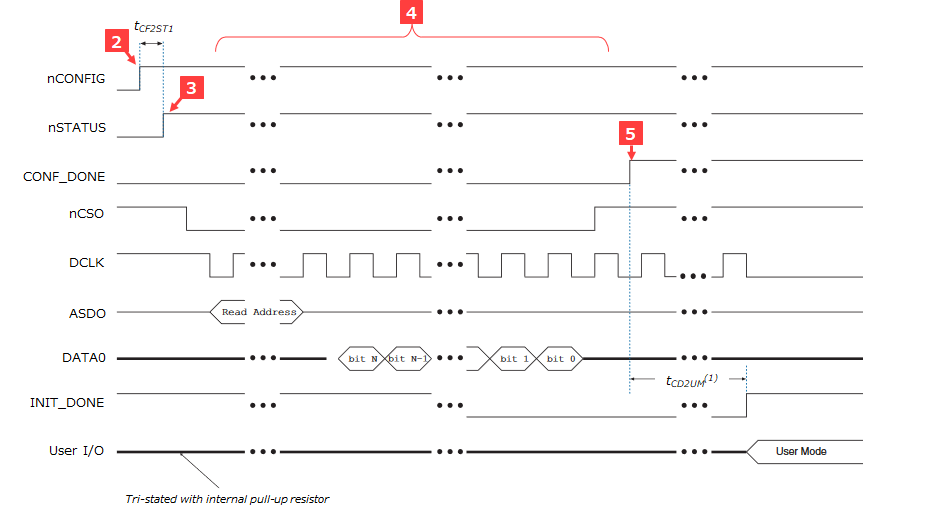
1. POR circuit monitors VCCINT, VCCIO, VCCA
2. The nCONFIG pin is pulled-up to VCCIO and is in a high state.
3. The nSTATUS pin is pulled-up to VCCIO to a high state.
4. DCLK and ASDO are output and data is sent on DATA0.
5. After receiving data, release CONF_DONE and pull-up to VCCIO to high state.
Configuration sequence when reconfiguring
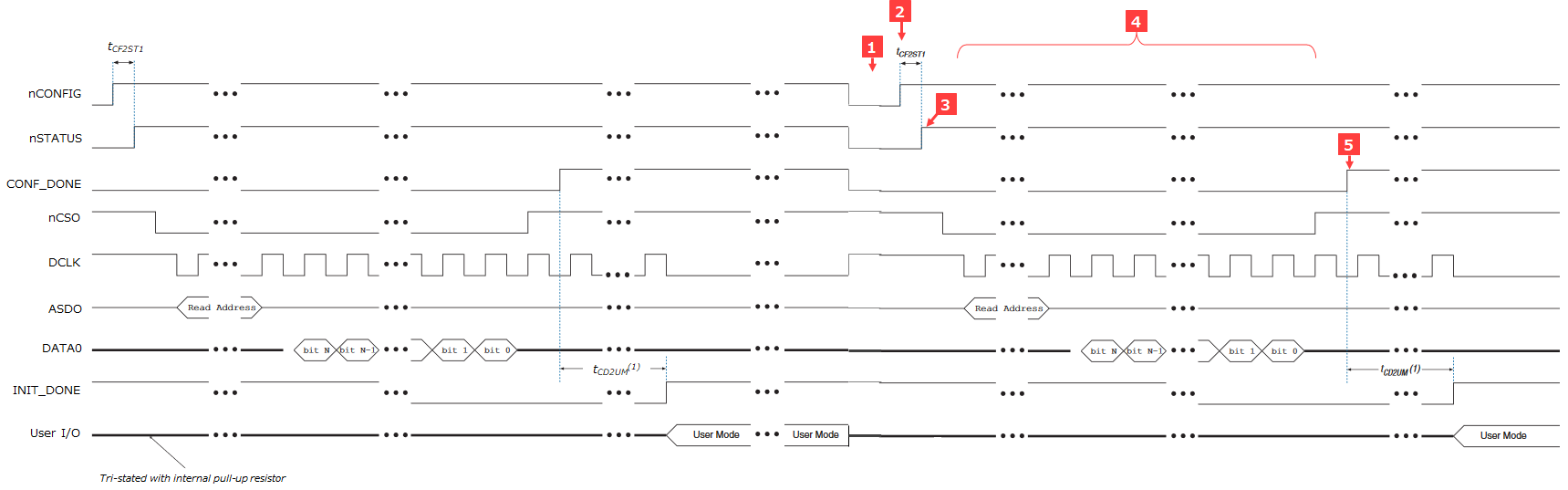
1. Drive nCONFIG low for more than 500ns
2. nCONFIG low to high
3. nSTATUS from Low to High
4. DCLK and ASDO are output and data is sent on DATA0.
5. After receiving data, release CONF_DONE and pull-up to VCCIO to high state.
Configuration sequence when configuration fails
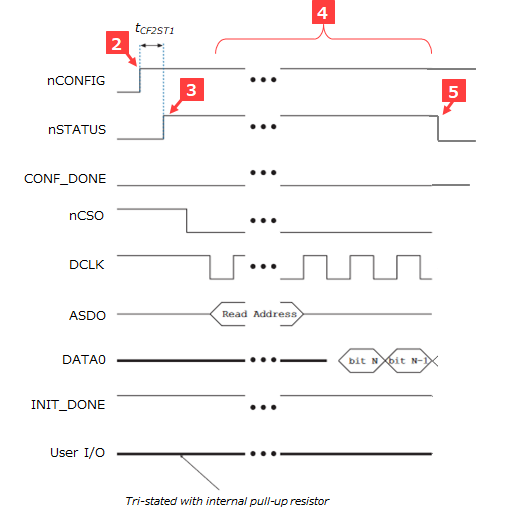
1. POR circuit monitors VCCINT, VCCIO, VCCA
2. The nCONFIG pin is pulled-up to VCCIO and is in a high state.
3. The nSTATUS pin is pulled-up to VCCIO to a high state.
4. DCLK and ASDO are output and data is sent on DATA0.
5. nSTATUS low
What Causes Configuration to Fail
What could be the reason for configuration failure? There seem to be two main reasons for this.
● Mistakes during tool operation
⇒ This is an artificial problem such as creating a sof file or setting the pinout constraints to a state different from that of the board.
● Substrate related issues
⇒ Two issues with signal quality and connectivity.
1) Problems with signal quality
This is when errors occur due to garbled configuration data due to reflections, crosstalk, noise, etc.
As a countermeasure, it seems necessary to consider the impedance and wiring length of the board wiring.
2. Connection problems
If the MSEL is not in AS mode, the AS mode configuration will fail.
Also, since nSTATUS and CONF_DONE are open-drain, there are connections required for configuration, such as requiring a pull-up resistor.
(Click here for configuration mode)
When I made a mistake in the production practice, I forgot to put a 25Ω series resistor on the DATA line of the Cyclone IV and had a hard time configuring it.
If the board is connected incorrectly, the following phenomenon will occur, resulting in a configuration error.
・ Does not recognize the configuration chain
・n STATUS stuck at High or Low
・ CONF_DONE does not go High
- DATA is not sent
・ DCLK is not output
After all, it is a deep configuration. . .