- Semiconductor BusinessHOME
- Products and Services of Macnica,Inc.
-
technical information

-
Events and Seminars
- Handling Manufacturer
- Support
- Inquiry
- Click here to purchase products
- Semiconductor business e-mail magazine registration
![]()
![]() Narrow down by specifying conditions
Narrow down by specifying conditions
現在2183件がヒットしています。check
background
Automotive systems continue to become more sophisticated with new features, changes and improvements introduced every year. Each function needs to be powered, protected and connected to its own interface within the overall automotive system. DCDC converters are required to convert the main 12V automotive battery power to the range of voltage levels required for the various functions to operate. DCDC converters are used in all types of vehicles to provide DC power for heavy loads in hybrid and electric vehicles, for lighting, displays, infotainment and other electronics.
Once powered and operational, automotive electronics are subject to a variety of transient events and must be tested to ensure compliance with standards such as ISO7637. Once properly protected, the electronics can be connected to the system using a variety of standard interfaces such as CANbus. It is important to ensure system reliability of these interfaces from an electromagnetic compatibility (EMC) and common mode noise (CMN) perspective. The protection of the system must be reconsidered after all interfaces are in place to ensure proper isolation and protection. Finally, electrostatic discharge must be considered as the electronics are subject to electrostatic discharge (ESD) events starting with the circuit assembly and continuing throughout the life of the vehicle.
Effective and reliable circuit protection is achieved by implementing a variety of resistive and magnetic materials for DC-DC converters, polymeric positive temperature coefficient (PPTC) devices for transient protection, common mode chokes and chip varistors for EMC and interface, and multilayer varistors and clamp devices for ESD protection. This article discusses the power, transient, interface and ESD requirements of components in the automotive environment. It also introduces various technologies and product families that have proven effective in protecting automotive electronics.
Stringent requirements for automotive systems
Electronics are increasingly replacing mechanical couplings in a wide variety of systems, including engine controllers, safety systems, chassis control, diagnostic systems, infotainment, etc. A variety of network interfaces, including CAN, Flexray, and Ethernet, connect each Electronic Sub-Assembly (ESA) to the system and to other ESAs. These ESAs are susceptible to interference and reliability issues caused by other ESAs.
While the variety of possibilities may seem to have little in common on the surface, all electronics, regardless of function, are powered from a single onboard battery and must withstand well-defined testing, surge and performance requirements throughout the life of the vehicle. In addition to a robust power conversion design, circuit protection is required to ensure that the electronics are not affected by external surges, other electronics in the system, or human interaction. Designing a stable and reliable system starts with understanding the needs and specifications of the conversion, interfaces and threats. Components can then be selected that address the requirements and meet or exceed the levels of performance and protection for each part of the onboard system.
Regulating the voltage levels of the power supply
DCDC converters are used in electronics to convert between voltage levels and provide a stable and accurate supply. A car running off a 12V battery has a nominal voltage of 14V. Some infotainment circuits require voltages to be stepped down to 5V or even 3.3V. Conversely, LED lighting strings need to be boosted to 60V, and permanent magnet DC motors, like those used in hybrid and fully electric vehicles, provide large loads of hundreds of volts.
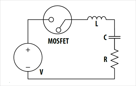
For these conversions, a power supply circuit usually includes a MOSFET, an inductor (L), a resistor (R) and a capacitor (C). The switch can represent a MOSFET as shown in Figure 1. In this circuit, the parasitic inductance of the wiring and the capacitance of the MOSFET combine and can interfere with the normal operation of the circuit. Components must be selected or inserted to minimize the risk of this interference and maintain stable operation of the converter and the system, whether the converter design is to increase or decrease the voltage delivered to the load.
Temporary Event Protection
A lot of consideration goes into protecting automotive electronics from various transient events. Transient surges that threaten automotive electronics are well known and are classified in ISO7637 according to the type of event. These events can last up to several seconds and generate hundreds of amps. Table 1 details the test specifications of ISO7637. Ri denotes the internal resistance of the voltage generator. Each ESA must be designed to pass the tests according to ISO7637. Designers must comply with the required level of protection by adding components to limit the surges and/or clamp the voltage.
|
test |
Simulation Contents |
Peak voltage (12V) |
Peak Energy (24V) |
|
1 |
Removing the battery from the power source |
-100 V (Ri = 10 Ω) |
-600 V (Ri = 50 Ω) |
|
2a |
Surge caused by wiring harness after current interruption |
+50 V (Ri = 2 Ω) |
+50 V (Ri = 2 Ω) |
|
2b |
DC motor as generator after ignition switch off |
+10 V (Ri = 0.05 Ω) |
+20 V (Ri = 0.05 Ω) |
|
3a、3b |
Inductive current due to wiring inductance |
-150 V (Ri = 50 Ω) |
-200 V (Ri = 50 Ω) |
|
4 |
Surge caused by starting motor current |
-7 V (Ri = 0.05 Ω) |
-16 V (Ri = 0.05 Ω) |
|
5a、5b |
Disconnecting a discharged battery while the alternator produces charging current (load dump) |
87 V (Ri = 0.5 Ω) |
174 V (Ri = 1 Ω) |
Table 1: ISO7637 test specifications
New challenges brought about by system interfaces
Proper protection as a standalone unit is the starting point for introducing an ESA into an automotive system. When connected to a system via an interface, the ESA can contribute to elevated network voltages. For example, most ESAs connected to a CANbus network include a common mode inductor to limit unwanted high frequency noise on the communication bus, improve the transceiver's immunity to EMC and reduce electromagnetic interference (EMI). In addition to all its benefits, the common mode inductor can also induce high voltages across the CANbus transceiver, as seen in ISO7637 test 1 disconnect from power. This voltage must be clamped by a suppressor, such as an automotive varistor, to protect the ESA from damage that an overvoltage condition can cause.
The inductor core, wire, construction and current flow selected will affect the electromagnetic emissions from the ESA. Emissions must be within guidelines specified by the vehicle manufacturer, which in some cases may be stricter than EN55022 Class B. This specification requires emissions levels to be 30dB (mV/m) in the frequency range 0 - 230MHz and 37dB (mV/m) from 230MHz to 1GHz.
Protection against electrostatic discharge events
Finally, electronics in the car must be protected from ESD damage. The risk of an ESD event is increasing with the availability of Universal Serial Bus (USB) for infotainment. There are three categories of classification of malfunctions caused by the current and voltage surges of an ESD pulse:
(i) A temporary error that is automatically corrected by the circuit or its operating system.
(ii) A transient error that requires operator intervention to recover and resume normal operation.
(iii) Permanent damage requiring partial repair or complete replacement.
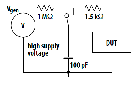
Similar to transient compliance, the automotive industry uses well-known standards for ESD protection guidelines. The Human Body Model (HBM) characterizes electrostatic surges with a current vs. time curve as shown in Table 2. It simulates the energy transmitted by human contact during handling on an assembly line. In testing, a surge generator can replicate the HBM curve by connecting a voltage source to a 1.5 kΩ resistor and a 100 pF capacitor, as shown in Figure 2. These tests help to incorporate proper voltage suppression into the design, such as Bourns® ChipGuard® chip varistors.
|
Applied voltage (kV) |
Peak Current (A) Human Body Model |
|
2 |
1.33 |
|
4 |
2.67 |
|
6 |
4.00 |
|
8 |
5.33 |
|
10 |
6.67 |
Solutions to help ensure reliability
Power Circuit Resistance
The first component inserted into a power supply for protection is a resistor. When the MOSFET switches, a voltage is induced across the capacitor. The formula is:
The peak amplitude of this sine wave is twice the supply voltage and can damage the MOSFET. Adding a resistor, R, in series with the MOSFET will dampen these oscillations and protect the MOSFET. The type of resistor used depends on the output power of the converter. The suitability of a resistor for your design depends on several factors:
First, the average power consumption 1 LC T pulse T period can be calculated using the following formula.
T pulse: Surge pulse length
T period: Time between surges
The total thermal resistance of the resistor and board is calculated using the following formula:
The temperature rise in the circuit is calculated using the following formula:
Finally, here is a graph of the energy a resistor can handle in Joules versus surge time: To calculate the energy of a surge, multiply the peak power of the surge by the duration of the surge and the relative area of the surge compared to a square pulse.
Bourns' fixed resistor portfolio includes AEC-Q200 qualified PWR series power resistors in a variety of packages. These thick film non-inductive resistors are electrically isolated from the backplate and are available in power ratings up to 50W. The low inductance of the Bourns® PWR163 and PWR263 makes them ideal for high frequency applications, and their excellent pulse characteristics support current limiting or capacitor discharge applications. The Bourns®4816P SOIC resistor network offers isolated, bussed and standard termination options with tolerances as low as 0.5%.
As an example of a resistor for a power supply circuit, assume Pav=9.2W and an operating temperature of 90 °C. If the resistor is a Bourns® PWR263S-35 and a typical high performance copper clad circuit board with a heat exchanger is used, the respective thermal resistances of 3.5 °C /W and 2.5 °C /W respectively add up to 6 °C /W. The temperature rise is 55.2 °C. The total temperature of the part is given by the sum of the temperature rise and the operating temperature. In this example, the resistor temperature is 145 °C, which is lower than the maximum temperature of 155 °C given in the Bourns® PWR263S-35 datasheet. The time vs. energy curve available in the datasheet indicates whether the part can handle the instantaneous power of the surge. If the resistor meets all these specifications, it can be incorporated into the design.
High Intensity Discharge Lamp
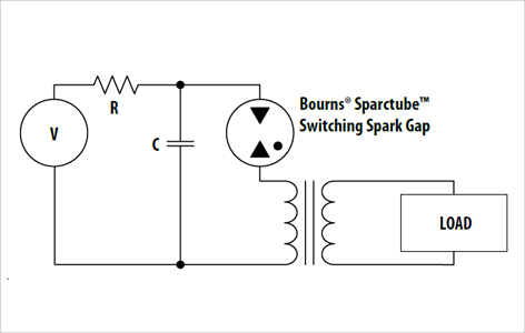
Another application of DC-DC converters is to supply the necessary lighting circuits in automobiles. High Intensity Discharge (HID) lamps require a very high ignition voltage pulse of several thousand volts followed by a constant voltage. A transformer coil and spark tube generate the high ignition voltage as shown in Figure 3. Bourns manufactures a series of high voltage spark tubes called Sparctube ™ Switching Spark Gap Devices for HID automotive lamp circuits. The Bourns® Sparctube ™ ST series is specifically designed for voltage controlled switching of capacitive discharge circuits where high energy, low loss and fast switching are required. This series operates at high temperatures and provides long term reliability. The most commonly used in automobiles are the 800V and 840V parts, Bourns® ST-0800-Bxx-STD and Bourns® ST-0840-Bxx-STD, respectively.
Implementing effective temporary protection
Bourns® Multifuse® PPTC devices are ideal for transient protection. Bourns® Multifuse® devices are thermistors with a non-linear resistance vs. temperature characteristic. The selection of a Bourns® Multifuse® PPTC device depends on the operating voltage (typically 16V for a nominal voltage of 14V), the operating current of the ESA application and the trip time as defined in the specification. During normal operation, the resistance of the device is very low and essentially invisible to the circuit. When the operating current of the PPTC reaches the trip current, the temperature of the device increases and the resistance jumps to a very high value.
Different polymer blends can be used in the manufacture of components to achieve specific features of the device such as high current capability (low resistance), high operating voltage, and high operating temperature. PPTC devices have a typical maximum operating temperature of 85 °C, although some Bourns® Multifuse® devices are rated to 125 °C. Bourns® components achieve a more stable resistance over a wider temperature range. This is a major advantage in situations where thermistor resistance plays a role in the circuit. One such example is the differential lines of a camera module. The bandwidth of the module can be affected by changes in PPTC resistance, so it is important to choose components that will not interfere with the proper operation of the circuit or trip prematurely.
Common mode inductors ensure low EMI levels
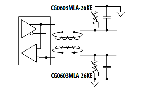
In a Common Mode Noise (CMN) choke, each inductor winding is connected in series with the input line. The connections and phases of the inductor windings are arranged so that the magnetic flux created by each winding cancels the magnetic flux of the other windings. Thus, the insertion impedance of the inductor to the input signal is zero, except for small losses in the leakage reactance and the DC resistance of the windings.
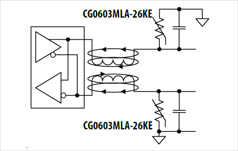
Instantaneous current is traveling in one direction as shown in Figure 4: in one input line and back through the other input line. The input current can pass through the common mode choke with almost no power loss because no voltage is developed in either winding due to the opposing magnetic flux generated in the core. Unwanted high frequency currents called common mode noise (CMN) can be generated in one or both input lines as shown in Figure 5. The CMN current returns to the noise source through the ground connection. Because it is not cancelled by the opposing return, this current sees the full impedance of one or both windings of the CMN inductor. To reduce the unwanted noise on the lines, the CMN voltage must be attenuated in the windings of the common mode inductor.
Inductors used in power interfaces and CAN transceivers must be shielded surface mount components capable of handling high currents. Bourns offers a wide selection of SRP family inductors. These shielded housings help achieve the low EMI levels required for automotive designs. The Bourns® SRP family of inductors combines flat wire technology with pressed powder cores to provide a compact and efficient package. Flat wire maximizes surface area for improved electrical conductivity, allowing for high frequency switching.
Preventing Overvoltage Damage
Bourns® ChipGuard® Multilayer Varistors are designed to provide optimum ESD protection in addition to acting as clamping devices in other areas of the automotive system. These devices have low capacitance and leakage characteristics that make them virtually invisible to the circuit during normal operation and can withstand multiple ESD events.
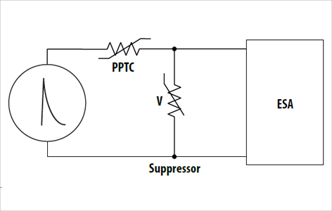
When an overvoltage condition occurs, the Bourns® ChipGuard® varistor clamps the voltage to a safe level, protecting the ESA from overvoltage damage. Suppressors, as shown in Figure 6, are connected across the terminals of the ESA to protect the electronics from ESD that occurs during board mounting or throughout its life. AEC-Q200 qualified varistors, such as the Bourns® CG0603MLC, are qualified using tests 1-3b of ISO7637. Selecting the correct Bourns® ChipGuard® device depends on the unique characteristics of the ESA to ensure the voltage and trip characteristics of the part meet the application requirements.
Achievements in automotive electronic components
Bourns has been a trusted supplier of electronic components for decades. Bourns resistors, magnetics, PPTC and fuse components meet the needs of automotive electronics designers in DC-DC converter design, transient and ESD protection, interface and system stability. All Bourns® components approved for automotive use are manufactured in facilities certified to TS16949. Components are tested and qualified using AEC-Q200, a well-known specification for passive components.
Once components are incorporated into the automotive electronics design, Bourns works with our automotive customers throughout the approval process, providing the documentation necessary to achieve approval while working toward achieving quality objectives. With a proven track record of quality, customer service and innovation, Bourns allows designers to focus on design.
Recommended related articles
- High power resistor PWR series *Redirects to manufacturer page.
- 4800P Series Thick Film Networks *Redirects to manufacturer page.
- Sparctube™ ST Series Switching Spark Gap Devices *Redirects to manufacturer page.
- SRP Series SMD Power Inductors *Redirects to manufacturer page.
- Multifuse® PPTC Resettable Fuses *Redirects to manufacturer page.
- ChipGuard® ESD Suppressors *Redirects to manufacturer page.
Inquiry
If you have any questions regarding this article, please contact us below.
Bourns Manufacturer Information Top
If you would like to return to the Bourns Manufacturer Information top page, please click below.