- Semiconductor BusinessHOME
- Products and Services of Macnica,Inc.
-
technical information

-
Events and Seminars
- Handling Manufacturer
- Support
- Inquiry
- Click here to purchase products
- Semiconductor business e-mail magazine registration


 Narrow down by specifying conditions
現在2240件がヒットしています。check

Altera® offers a PDN (Power Distribution Network) tool that analyzes the impedance fluctuations caused by the resonance of multiple capacitors, as described above, using the actual types and number of capacitors. Since it's Excel-based, no special installation is required, making it easy to try out.
This time, I will explain how this tool works.
If you'd like to try the tool, you can download it from here.
Power Supply Network (PDN) Tools User Guide
User Guide
Signal and power integrity support
Altera® FPGA Signal Integrity and Power Integrity
circuit topology
Figure 1 shows the circuit topology and Figure 2 the equivalent circuit.
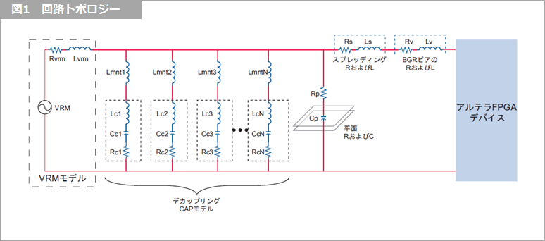
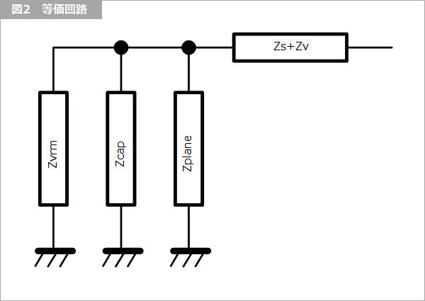
Figure 3 shows the impedance characteristics of each block and the overall equivalent power impedance.
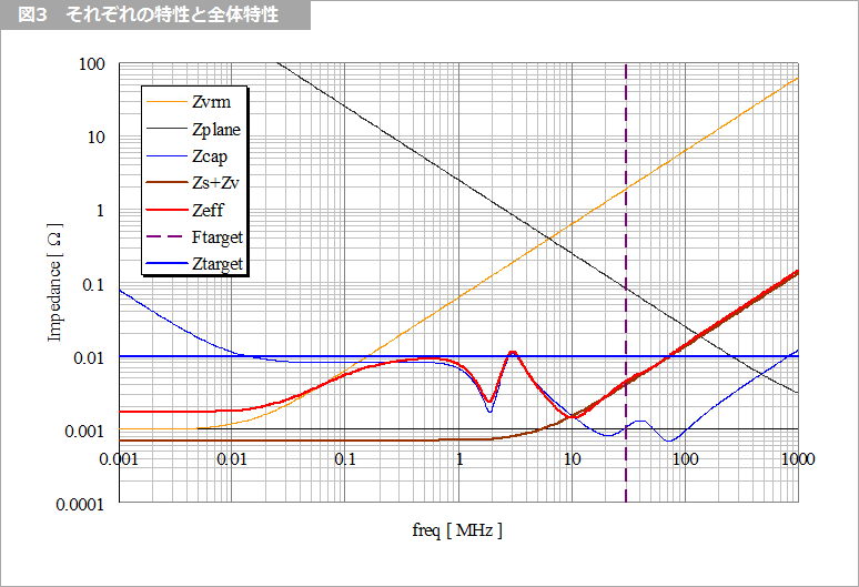
The PDN tool sets frequency and impedance targets and determines the type and number of capacitors to meet them.
I will describe each element.
(1) Power Supply Module VRM (Voltage Regulator Module)
It's literally a power regulator.
A voltage is output in series with the ideal power supply via resistor Rvrm and inductor Lvrm.
Since Rvrm takes a very low value at low frequencies, it contributes to the impedance reduction in the low frequency region in the power supply system. However, from a certain frequency, it increases in proportion to the frequency, so I will pass the baton to "(2) Decoupling capacitor".
Rvrm and Lvrm are obtained from VRM manufacturers.
In the characteristics of Figure 3, we denote it as Zvrm. Contributes to low frequency characteristics.
(2) Decoupling capacitor
It is a parallel connection of several capacitors mentioned so far.
By using a large number of capacitors with different values, the overall impedance peaks are suppressed and flattened over a wide frequency range.
An inductor connected in series with a capacitor is expressed as the sum of the ESL (Equivalent Series Inductance) of the capacitor itself and the Lmnt generated when it is mounted on the board.
(3) Power layer capacitor
Power-Ground forms a parallel plate capacitor. Its capacity is
C = εLW/h
can be expressed as
where ε is the dielectric constant, L and W are the length and width, and h is the power-to-ground distance. If two ground planes sandwich the power plane, the capacitance is the sum of their respective capacities.
The resistance is a rectangular shape with length L being the longer side and width W being the shorter side.
R = ρL/Wt
to find it.
ρ is the resistivity, which is 1.72 × 10^-8 for copper at 25 °C.
(4) Connection between power supply layer and IC
Resistors and inductors are connected in series with multiple capacitors.
Overall characteristic (Zeff) is (4) connected in series for parallel connection of (1) to (3). Since each impedance is a complex number, it is calculated using Excel's complex number function.
In the overall characteristics (Zeff) of Figure 3, the impedance increases at high frequencies, but in this area power supply noise is suppressed by the internal capacitance of the IC, so the upper frequency limit Ftarger is given.
What is Yuzo Usui's Specialist Column?
It is a series of columns that start from the basics of the basics, and include themes that you can't hear anymore, themes for beginners, and even a slightly advanced level, and describe them in as easy-to-understand terms as possible.
Maybe there are other themes that interest you!