- Semiconductor BusinessHOME
- Products and Services of Macnica,Inc.
-
technical information

-
Events and Seminars
- Handling Manufacturer
- Support
- Inquiry
- Click here to purchase products
- Semiconductor business e-mail magazine registration


 Narrow down by specifying conditions
現在2240件がヒットしています。check

Hello! I'm Power-chan, a new graduate FAE who joined in 2025.
I majored in biology in university and hadn't even taken basic physics in high school, so I had zero knowledge of electrical and electronic devices. I took on the challenge of building a robot in three months. In this blog, I'll share my struggles over the three months from scratch, as well as the typical mistakes and failures of a newbie!
The theme this time is "Anode and Cathode of Diode".
Robot construction with only 3 months
Before we get to the main topic of diode anodes and cathodes, let me first give a brief explanation of this construction workshop.
Every year, new FAEs learn circuit design and software knowledge through hands-on production training.
The theme of this workshop was "Development of a maze escape machine." This machine uses a sensor to detect walls and navigate automatically through a maze. If you're having trouble visualizing it, try searching for "micromouse" and you'll probably get a better idea.
The most detailed explanation of the micromouse (Source: Japan System Design Co., Ltd.)
Micromouse is a type of official robot competition, with national championships. Apparently, participants usually spend about a year preparing to build their own mouse, but we were only given three months. Even if we weren't expected to build a robot at a level that could compete in the national championships, isn't three months too short? When I heard about this plan, I honestly thought, "There's no way I could complete a robot," but it turns out people can do it if they put their mind to it. Here's the robot we actually built. We created a very cute robot with a cheetah concept.
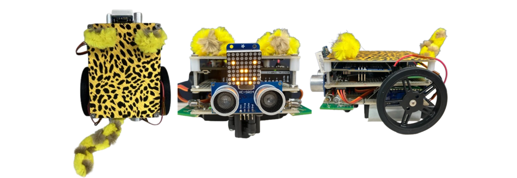
The actual robot
Basically, we were allowed to build anything we wanted as long as it was within our budget, but the only specification requirement was: Analog DevicesSwitching type of DCDCImplementing a converter on a universal board That's what I mean. This is so difficult (tears). FAE I've often thought, "Maybe it was a big mistake to become like that..." However, this story would take too long to explain, so I'll save it for another time.
This time I 9V Battery voltage DCDC With a converter 5V and the motor Infrared sensor The infrared sensor used this time is SFH 4550 That Infrared LED and ST-1KL3A That Phototransistor It was created by combining
It's finally here. This introduction has been quite long, but this leads us to the topic of anodes and cathodes.
infrared sensor
The infrared sensor mentioned earlier was used to detect walls. In the production workshop, the students had to consider all of the parts and specifications they would use, so each builder ended up with a robot that looked completely different, with different parts and specifications.
Infrared sensors are also used in actual micromouse competitions, and the combination of LED and phototransistor used this time has a proven track record, so I thought maybe I could use this too!!
How infrared sensors work
Here is a brief explanation of how the infrared sensor works.
First, the infrared LED emits infrared light forward. This infrared light hits the wall and reflects, and the phototransistor detects the reflected light. The distance to the object is estimated from the intensity and angle of this reflected light.

How infrared sensors work
Generally speaking, the stronger the reflected light, the closer the wall is, and the weaker it is, the farther away it is. It's a pretty simple and easy-to-understand system.
Anode/Cathode
Sorry for the wait. Now we can finally talk about the main topic, the anode/cathode problem.
LEDs have a polarity known as anode and cathode. Since current flows from the anode to the cathode, the anode must be connected to the positive side and the cathode to the negative side. If the connection is incorrect, the current will not flow, which can even damage the LED depending on the type and voltage, so it is important to be careful.
So how do you distinguish between an anode and a cathode? Generally, the longer leg of a diode is the anode, and the shorter leg is the cathode.

Which is the anode?
Because I had learned this information in training prior to the production workshop, when I was building a test circuit on a breadboard to check the operation of the infrared sensor, I got to work enthusiastically, saying, "The longer one is the anode!!" This is the test circuit I actually created.

Infrared sensor test circuit
When I put this circuit together, I thought that the current would flow from hole j to hole f, and from hole e to hole a, so I wired the wires in exactly the right order, which resulted in a pretty messy layout. This is another typical rookie mistake.
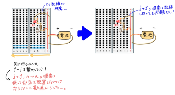
Misunderstanding diagram (only LED circuit for simplification)
That aside, even though the circuit was correct, we encountered a problem where infrared light was not being emitted from the LED. Some of you may be wondering, "Infrared light is invisible to the naked eye, so how did you know it wasn't being emitted?" In fact, you can easily check this by using your smartphone camera! And it's super simple! Just look at the infrared LED through your smartphone camera! Smartphone cameras and digital cameras can visualize infrared light, so if you see a white or purplish light on the screen, you can confirm that infrared light is being emitted.
*Some cameras may not be able to check this.
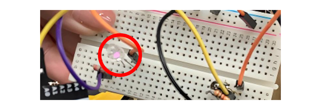
Infrared rays emitted from an LED seen through a camera
Test Circuit LED When I actually looked at it through the camera, I could not see any light, even though I should have seen a pinkish light as in the image above, so I concluded that no infrared light was being emitted. I wondered if I had installed the anode and cathode in the wrong place, so I removed it and checked, but it was not working properly. Connect the longer end to the positive side No matter how many times I checked the circuit, I couldn't find anything strange. LED When I checked the data sheet, I found that LED teeth The shorter one is the anode I never thought that the longer one was the anode. 1 I never thought it would be overturned in less than a month. LED I changed the direction and reconnected it, and it worked just fine. LED Fortunately, I was able to notice it before it broke. LED Really? 1 Current can only flow in one direction.
Summary
First of all, read the datasheet!!
This is the biggest lesson I learned from this failure. You should never be overconfident in your knowledge. I will keep this in mind as a lesson for the future.
To all you newbies out there reading this, we recommend that you always read the product datasheet when attempting to create something!
That was the first of new FAE Power's adorable failure stories!
Power-chan article list
・Don't be fooled by appearances - Anode and cathode edition
・ Don't get caught up in short-term profits - Power supply design edition
・ Be careful of exposed solder! ~Component interference edition~