- Semiconductor BusinessHOME
- Products and Services of Macnica,Inc.
-
technical information

-
Events and Seminars
- Handling Manufacturer
- Support
- Inquiry
- Click here to purchase products
- Semiconductor business e-mail magazine registration
![]()
![]() Narrow down by specifying conditions
Narrow down by specifying conditions
現在2162件がヒットしています。check

With the need to strengthen factory networks, the new industrial Ethernet standard "10BASE-T1L" is attracting increasing attention.
"I know the name 10BASE-T1L, but I want to check the features again" "I want to know the comparison with 4-20mA and fieldbus" "I want the PHY information necessary to build a system with 10BASE-T1L" Isn't there a lot of people?
Here, we introduce an overview of "10BASE-T1L", a comparison with conventional methods, and a lineup of dedicated "10BASE-T1L"PHYs for engineers who want to renovate their factory networks.
- Continuous evolution of factory networks - 10BASE-T1L, a new standard for industrial Ethernet
As we enter the era of Industry 4.0, manufacturing DX and smart factories are being promoted, and the 4-20 mA HART communication and fieldbus communication that have been used in factories so far cannot cope with the increase in data volume. There is a problem that "real-time data transmission is not possible".
In addition, with the advent of IoT, the communication distance has become longer, and the complexity of wiring has become unavoidable in many factories. From the perspectives of "not wanting to make wiring more complicated" and "wanting to reduce cable costs," there is a demand for Ethernet communication.
Under these circumstances, the new industrial Ethernet PHY standard "10BASE-T1L" has emerged. It was approved as "IEEE 802.3cg" on November 7, 2019.
Its main specifications are expressed in the name "10BASE-T1L".
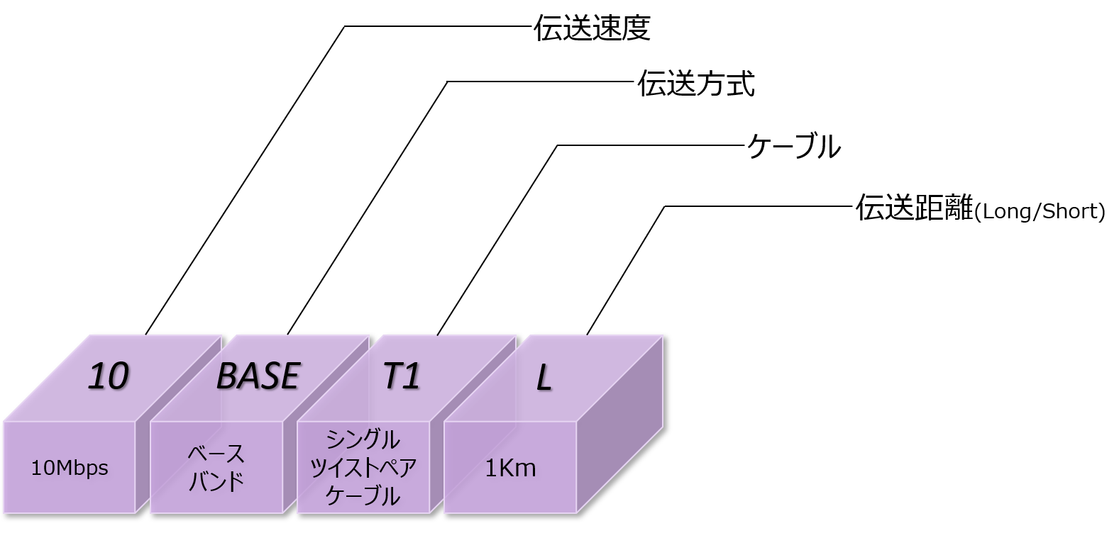
It is characterized by the ability to achieve long-distance communication up to 1km with a pair of twisted pair cables.
The transmission speed is 10Mbps, and it supports full duplex communication and point-to-point connections. Power can also be supplied via cable.
It is also intrinsically safe and can be used in production area applications where protection against fires and explosions caused by flammable gases and dust is required.
Differences from the standard industrial Ethernet PHY standard are shown in the table below.
| PHY main function | 10/100/1000 | 10BASE-T1L |
| cable | 2-pair or 4-pair Ethernet | Single pair Ethernet |
| distance | up to 100m | up to 1km |
| Explosion proof | incompatible | Correspondence |
| Transmission speed | 10Mbps,100Mbps,Gbps | 10Mbps |
| connector | RJ45 |
No regulations. Small 2-pin connectors are acceptable |
| power supply | Supports PoE | Supported by PoDL |
<Comparison: Standard PHY and 10BASE-T1L>
Using 10BASE-T1L, it is possible to connect simply via Ethernet from terminal devices to control devices, and reduce the weight and cost of connectors and cables.
Differences between "10BASE-T1L", "4-20mA HART" and "Fieldbus"
So, what are the features of 10BASE-T1L compared to conventional 4-20mA HART communication and fieldbus communication?
The table below summarizes this.
| Comparison item | 4-20mA HART | field bus | 10BASE-T1L |
| network bandwidth | 1.2kbps | 31.25kbps | 10Mbps |
| Connection with upper layer Ethernet | Requires a gateway | Requires a gateway | No gateway required |
| power supply | less than 40mW | Limited |
Explosion proof: 500mW Non-explosion proof: 60W (depends on cable) |
| number of technicians | downward trend | downward trend | Ethernet technology with many young learners |
<Comparison: "4-20mA HART" "Fieldbus" "10BASE-T1L">
Features (1) 10Mbps bandwidth to accommodate data growth
4-20mA Compared to HART communication and fieldbus communication, 10BASE-T1L has an overwhelmingly wide network bandwidth. Acquire data directly from sensors and actuators in remote locations and collaborate in real time.
Features (2) No gateway required, long-distance communication of 1 km
Until now, data linking from end devices to upper Ethernet layers often required gateways to aggregate data in the middle. 10BASE-T1L supports 1 km long-distance communication and enables point-to-point connections, enabling seamless connections without the need for gateways.
Features (3) Significantly increased amount of power supplied via cable
10BASE-T1L can supply power via cable up to 500mW for explosion-proof models and 60W for non-explosion-proof models. Simple wiring greatly increases power supply to sensors and actuators.
Features (4) Ethernet technology with many young engineers
In Japan, engineers are aging, and the number of engineers who can handle legacy communication standards is decreasing. There are many engineers who are familiar with Ethernet technology even though they are young, so it can be deployed without difficulty in transferring know-how and technology.
Features (5) Reduce costs by reusing cables
Since there is no specific cable specification, existing cables may be reused if simple specifications such as insertion loss and return loss are met. Cable costs can be reduced and wiring can be reduced.
By using 10BASE-T1L, it is possible to realize a seamless network environment for the entire factory that supports Industry 4.0 in the future.
Analog Devices' 10BASE-T1L dedicated PHY lineup
What specific devices are required when implementing 10BASE-T1L?
Here, we will introduce three products from ADI's industrial 10BASE-T1L PHY lineup, which features ultra-low power consumption.
ADIN series naming convention
First, let's organize how to interpret the product lineup. Analog Devices' industrial 10BASE-T1L PHY lineup has model numbers that start with "ADIN," and the key specifications can be determined simply by looking at the four digits that follow. Counting from the left, the first digit is the number of channels, the second digit is the speed class, the third digit is PHY or MAC-PHY, and the fourth digit is the variation, making it easy to organize the lineup.
ADINXXXX
|
Number position (from left) |
meaning |
Main Values |
|
1st (X xxx) |
Number of PHY channels |
1: Single 2: Dual |
|
Second (x X xx) |
Speed Class |
1: 10Mbps compatible (10BASE-T1L only/long distance, low speed) 2: Supports 100Mbps (10BASE-T1L+100Mbps * cable length 180m) 3: Supports 1000Mbps (10BASE-T1L + 100Mbps + 1GbE * Cable length 150m) |
|
Third (xx X x) |
PHY or MAC-PHY |
0: PHY only 1: MAC-PHY integrated type (SPI control, etc.) |
|
4th (xxx X) |
Variations |
0: Simple product 1: Functional products |
Example 1) Both the ADIN1100 and 1101 are standalone PHYs, but the 1101 is smaller and has built-in termination resistors.
Example 2) Both the ADIN1110 and 1111 are MAC-PHYs, but the 1111 is smaller and has built-in termination resistors.
ADIN: Analog Devices Industrial Networking product series
Lineup (1) "ADIN1101" with ultra-low power consumption and built-in termination resistor
The ultra-low power ADIN1101 is a PHY compliant with IEEE 802.3cg-2019 and supports 1.0V pk-pk and 2.4V pk-pk operating modes.
While maintaining the same ultra-low power consumption performance as the previous model, the ADIN1100, the package size has been further reduced to just 5x5mm.Since the termination resistor is built-in, external resistors can be eliminated, contributing to a reduction in the number of components and a more compact system.
By enabling the auto-negotiation function, it supports cable transmission distances of up to 1700 meters and achieves ultra-low power consumption of 39mW.
- Compliant with 10BASE-T1L IEEE 802.3cg-2019 standard
Supports 1.0 V p-p and 2.4 V p-p transmission modes
・Super power consumption: 39mW~
- Supports cable lengths up to 1,700m with auto-negotiation
Small package: 32-lead 5mm x 5mm LFCSP
Guaranteed industrial operating temperature range: −40°C to +105°C
Lineup (2) Small MAC/PHY "ADIN1111" compatible with SPI interface
Next, we will introduce the ADIN1111, a PHY with built-in MAC. It can communicate with the host processor using the SPI protocol, making it easy to use and significantly expanding the range of processor options. The architecture and software of current solutions can be reused as is, reducing design effort.
The package size is 5x5mm, which is even smaller than the previous model, the ADIN1110. The built-in termination resistor eliminates the need for external resistors, contributing to a reduction in the number of components and space savings for the entire system.
・Complies with 10BASE-T1L IEEE 802.3cg-2019 standard
- Supports 1.0 V p-p and 2.4 V p-p transmission modes
-Master/Slave
- Built-in SPI interface MAC
- Supports IEEE 1588 timestamps
・Ultra low power consumption: 50mW~
- Supports cable lengths up to 1,700m with auto-negotiation
Small package: 32-lead 5mm x 5mm LFCSP
Guaranteed industrial operating temperature range: −40°C to +105°C
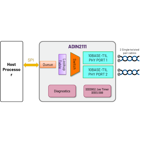
Lineup (3) "ADIN2111" for easy daisy chain connection
"ADI2111" has two PHY ports. A single device enables easy and low-cost daisy-chaining. Built-in MAC enables SPI communication with host processor.
For example, it is suitable for a comprehensive building management network because it can be easily connected to a building temperature and humidity measuring device.
・Simple Ethernet switch
-Cut-through and forward operation
-On-chip FIFO/Queue
-RX:20KB、TX:8KB
・SPI host interface
-16 MAC addresses
-10Mb/sec full duplex
・Low power consumption: 80mW (1v p-p dual power supply)
- Small package: 48-lead 7mm x 7mm LFCSP
・Complies with 10BASE-T1L IEEE 802.3cg-2019 standard
Product comparison table
Below is a comparison table of the products introduced so far. For comparison, the "ADIN1101 / ADIN1111" also includes the previous models "ADIN1100 / ADIN1110."
|
product |
type |
interface |
Maximum Cable Length |
Supported Bandwidth |
power consumption |
Package/Size |
Temperature compatibility |
|
ADIN1100 |
PHYs |
MII / RMII / RGMII + MDIO |
1,700 m |
10BASE‑T1L (10 Mbps) |
39 mW |
40-pin LFCSP / 6×6 mm |
–40~+105 ℃ |
|
ADIN1110 |
MAC‑PHY |
SPIs |
1,700 m |
10BASE‑T1L (10 Mbps) |
42 mW |
40-pin LFCSP / 6×6 mm |
–40~+105 ℃ |
|
ADIN1111 |
MAC‑PHY |
SPI + Open Alliance |
1,700 m |
10BASE‑T1L (10 Mbps) |
50 mW |
32-pin LFCSP / 5×5 mm |
–40~+105 ℃ |
|
ADIN1101 |
PHYs |
MII / RMII |
1,700 m |
10BASE‑T1L (10 Mbps) |
39 mW* *Low power consumption mode available |
32-pin LFCSP / 5×5 mm |
–40~+105 ℃ |
|
ADIN2111 |
2-Port Switch |
2 × 10BASE‑T1L PHY + SPI MAC/Switch |
1,700 m |
10BASE‑T1L (10 Mbps) |
77 mW |
48-lead LFCSP / 7×7 mm |
–40~+105 ℃ |
If you are currently using the conventional products "ADIN1100 / ADIN1110", migrating to the functional products "ADIN1101 / ADIN1111" is also a valid option.
The ADIN1101/ ADIN1111 incorporate a termination resistor, reducing the four transmit/receive terminals found on previous models to two. The power supply voltage terminal (DVDD1P1) has also been eliminated.
Migrating from conventional products offers benefits such as a smaller package, fewer peripheral components, and a simpler circuit configuration. Although changes to the board are required, such as removing external resistors, the software, drivers, and registers can be used with the same settings as the conventional product.
This reduces the design load while also saving space and reducing the number of parts.
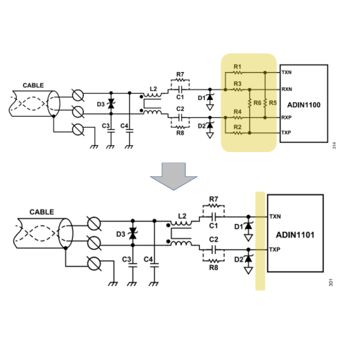
ADIN1100/ADIN1110⇒ADIN1101/ADIN1111
Migration Summary
Design changes required
・PCB (smaller size)
- Eliminates external resistors (termination resistors are built-in)
・Addition of power supply voltage (DVDD1P1)
No changes required!
・Software/driver settings
・Register settings
Enhanced diagnostic functions reduce downtime
All of the devices introduced here have enhanced diagnostic functions, allowing for quick response in the event of network problems and reducing system downtime.
Link quality monitoring also allows SNR measurement and bit error rate estimation, and supports loopback, frame generator, and frame checker. The built-in cable diagnostic function, TDR (Time Domain Reflectometry), allows you to analyze the location and type of faults.

The evaluation board can diagnose the communication quality of existing cables.
Because there are no standard cable regulations for 10BASE-T1L, it is possible to reuse existing single-pair cables as long as they meet a certain level of communication quality. By utilizing existing wiring as is, you can strengthen your factory network while keeping installation costs down. However, there may be cases where you are unsure whether you can actually use existing cables.
Analog Devices offers a signal quality diagnostic function using evaluation software (GUI), which makes it possible to quantitatively determine whether the existing wiring is actually usable.
Cable diagnostics by MSE (Mean Square Error)
Cable diagnostics using the evaluation board uses MSE (Mean Squared Error). MSE is measured inside the PHY, and link quality is evaluated using SNR (Signal-to-Noise Ratio) and BER (Bit Error Rate).
Analog Devices PHY devices store a value in the MSE_VAL register every 133 nS. By applying this value to the formula, you can calculate the MSE and SNR.
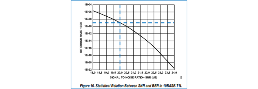
There is a correlation between SNR and BER, as shown in the graph below.
The IEEE 802.3cg-2019 standard requires a BER of 10⁻⁹ or less. The horizontal dashed blue line indicates a BER of 10⁻⁹. According to this graph, the BER meets the standard requirement when the SNR is 20dB or more. Using the formula above, this can be interpreted as an MSE of -20dB or less.
To easily measure MSE, the evaluation board is equipped with a frame generator/checker function and a loopback function.
Frame generator/checker function
The frame generator function can be used to generate test frames. The evaluation software (GUI) allows detailed settings of frame length and data type.
The frame checker function allows you to verify received frames. Errors are counted by type and can be checked on the evaluation software (GUI).
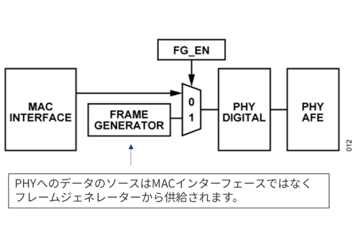
Frame Generator Function
Frame checker function
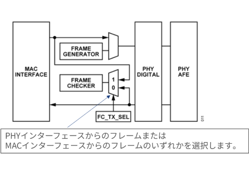
Loopback function
The loopback function allows the received signal to be looped back directly within the PHY. By looping back a test signal, the frame checker function can be used to check whether the sent signal is returned correctly.
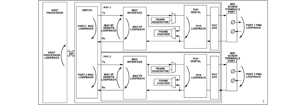
The loopback point can be selected from a variety of points. If an error occurs, you can isolate the cause of the error by gradually changing the loopback point. The loopback point can be set using the evaluation software (GUI).
Cable diagnosis flow using an evaluation board (example)
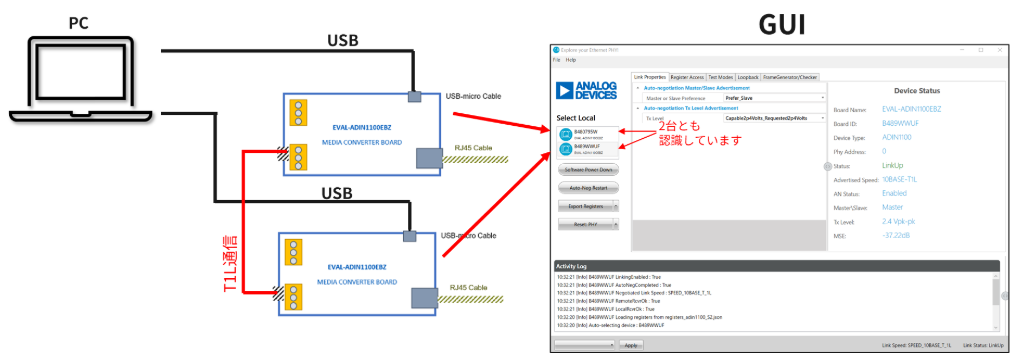
Below is an example of a connection for cable diagnosis using two evaluation boards (EVAL-ADIN1100EBZ). The two evaluation boards are connected to one PC via USB, and the cable to be diagnosed is used to connect the evaluation boards together. Each board is assigned a unique ID, so they can be recognized as separate boards even when connected to the same PC.
In the evaluation software (GUI), set one of the boards to loopback mode. In this example, loopback is set on the MAC I/F.
The other is set as a "frame generator/checker" that generates test signals. Specify the frame length and data type to be generated.
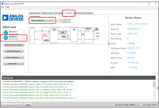
Set one side to loopback via MAC I/F
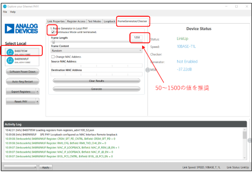
Set the other one as a frame generator/checker
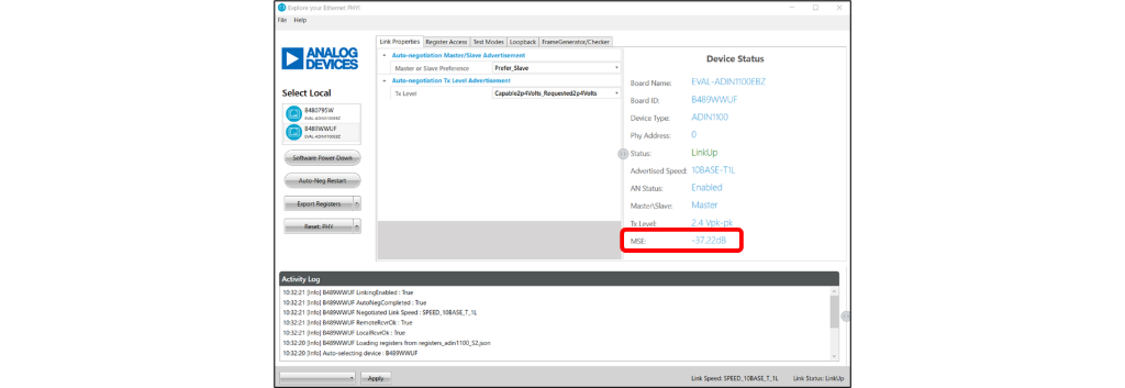
Pressing the "Generate" button on the evaluation software (GUI) will start the communications test. The number of frames received via loopback, the number of errors, and the MSE will be displayed on the screen.
In this example, the MSE is below-20dB, so the cable quality is considered to be satisfactory.
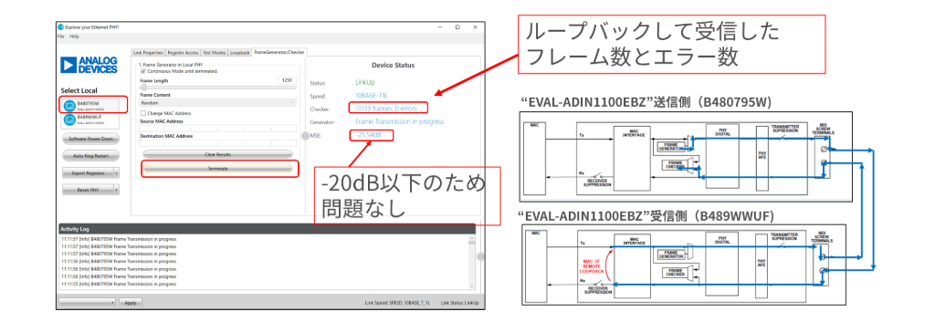
In this way, two evaluation boards are used to provide a mechanism for easily diagnosing the quality of cables.
By utilizing this function, you can check in advance whether the existing cable meets the 10BASE-T1L communication quality. This not only allows you to determine early on whether rewiring work is necessary, but also minimizes the risk of unexpected problems and rework on site.
To ensure the successful implementation of 10BASE-T1L, please take advantage of cable quality diagnosis using an evaluation board.
Electrical isolation solution for use with PHY
Macnica carries various products from Wurth Electronics as electrical isolation solutions required by 10BASE-T1L.
Compliant with the IEC 62368-1 standard, it can be used as a peripheral part of ADI's PHY device for transformers, common mode chokes, diodes, capacitors, etc. in the circuit up to the external Ethernet connector. contributes to the simplification of Please consider it together.
Evaluation boards are available for each of the devices introduced in this article. Two boards are provided, so you can use it as a master and a slave and try it easily.
If you are interested, please feel free to contact us.
Application example
・Factory network
Click here to purchase products
Click here for manufacturer site/other related sites
- Ethernet Transceivers & Switches (Download all data here)
- Deployable 10BASE-T1L Single-Pair Ethernet Condition-Monitoring Vibration Sensor Design
- The New 10BASE-T1L Standard – What Has Changed?
- "10BASE-T1L" enables analysis of big data at the edge
- 10BASE-T1L MAC-PHY Simplifies Ethernet Connectivity for Low-Power Processors
- 10BASE-T1L enables seamless Ethernet connectivity for field devices
- What are the specifications required for an industrial Ethernet PHY? ADIN1200/ADIN1300
- Smaller, lighter, and easier to design than conventional products! Single Pair Ethernet Solution
Inquiry
If you have any questions regarding this article, please contact us below.
Analog Devices Manufacturer Information Top
Analog Devices Manufacturer Information If you would like to return to the top page, please click below.