- Semiconductor BusinessHOME
- Products and Services of Macnica,Inc.
-
technical information

-
Events and Seminars
- Handling Manufacturer
- Support
- Inquiry
- Click here to purchase products
- Semiconductor business e-mail magazine registration
![]()
![]() Narrow down by specifying conditions
Narrow down by specifying conditions
現在2183件がヒットしています。check

No matter what kind of system development you are doing, you need a power supply circuit design. When designing a board that includes an FPGA, it may be necessary to mount 5 or more regulators.
Regulators include linear regulators and switching regulators (or DC/DC converters). For the difference between a linear regulator and a switching regulator, please refer to the newcomer's blog "Which is better? ~Linear and switching~".
There are also step-down and step-up regulators (for the difference between step-down and step-up, refer to the blog for newcomers "DC-DC Converter - Secrets of Voltage Conversion"), but for boards with FPGAs, step-down type is mainly used. A switching regulator is used, so this time I will introduce the design procedure and verification method for a step-down switching regulator.
Switching regulator selection and circuit diagram
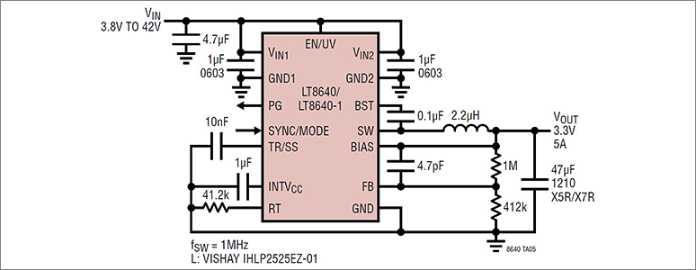
For example, consider the case where input VIN=12(V) output VOUT=3.3(V) load current IOUT=4(A) is required.
Considering the 80% derating, select a product with a load current of 5(A) [=4(A)÷80%].
We selected the LT8640 based on the required specifications.
Once you have decided which switching regulator to use, the first thing you should check is the datasheet. There are Japanese and English versions. There is no problem if you look at the Japanese version, but please be sure to check the English version.
Analog Devices datasheets have many reference schematics.
From the data sheet, select a circuit diagram that matches the required specifications (Fig. 1).
When there is no reference circuit for the required specifications, or when checking peripheral constants
If there is a reference circuit diagram, it is possible to apply it to the actual circuit as it is.
However, just in case, please use the calculation formula in the application information section of the data sheet to check if there are any mistakes in the circuit constants.
If you don't have a reference schematic, there are two ways to design.
The first method is to design the circuit using the calculation formulas in the application information section of the datasheet.
The circuit design procedure for a typical step-down DC/DC converter is summarized in "Constant Calculation and Notes for Step-down DC/DC Converters".
Use this as a reference when designing.
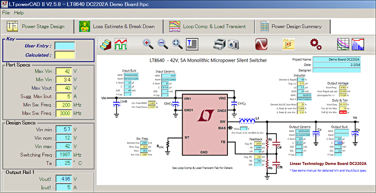
The second method is to create a schematic using LTPowerCAD from Analog Devices.
Compensation circuits can also be designed using LTPowerCAD.
If you have decided which device to use, refer to the article "Can you create a power supply circuit just by inputting the power supply specifications?" and use LTPowerCAD to design the circuit. If you have not decided which device to use, refer to "Let's use the convenient design tool LTpowerCAD!"
If you want to know how to design the peripheral constants of switching regulators, we recommend taking the Power Supply Design Seminar Introduction.
Verification of switching regulator operation
Even if a circuit diagram is created, it is necessary to check whether the actual noise performance and efficiency match the expected characteristics.
We recommend that you obtain an evaluation board from Macnica Mouser, etc. and check the operation on the actual device.
For reference, the LT8640 evaluation board DC2202A can be purchased here.
Even if the capacitor capacity is the same, the characteristics of the power supply obtained will vary depending on the manufacturer and model number used, so we recommend verifying it with an actual device just to be sure.
How to verify the circuit before getting the demo board
It is best to verify with a demo board, but if it takes time to obtain it or if you want to verify the circuit diagram on the same day, you will be in trouble.
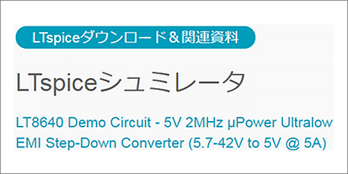
In such cases, it is possible to perform circuit verification using LTspice, which is provided free of charge by Analog Devices.
Download LTspice here.
If you install LTspice on your computer, you can perform circuit verification on the simulation.
Also, if you want to verify the circuit of the demo board on LTspice, the LTspice circuit of the demo board is posted on the Analog Devices product page as shown in Figure 3. Please use it effectively.
If the desired simulation results are not obtained when the circuit is verified on LTspice, there is a high possibility that there is a problem with the circuit.
In such a case, check the circuit diagram to see if the connections are correct. Are there any differences in the settings of the peripheral constants? It is important to check etc.
Everything is decided by pattern design!
I've created a schematic, and the results on LTspice are as expected, so I'd like to say, "The design is complete!"
A switching regulator's performance is determined by its pattern design.
Even if you copy and use the circuit diagram recommended by Analog Devices, or use the circuit diagram that worked with LTspice, if there is a mistake in the pattern design, the noise will increase or the switching regulator will not work (worst case) , it will be corrupted).
To avoid such problems, check the following two things when designing patterns.
- Follow the recommended layout notes in the datasheet
- Design based on the pattern/layout information in the design file of the demo board
Please be sure to check the design information of the demo board because the pattern layout in the datasheet may be written simply.
LT8640 design information can be found at this link
Also, it is very important not to leave the pattern design to the person in charge of CAD, but to check again whether the pattern design is the same as the demo board.
If there is no problem at this point, let's wait for the completion of the board.
Click here for recommended seminars/workshops
[Online Seminar] Analog Solution Power Supply Design Seminar <free>
[Online Seminar] Analog Solution Thermal Design Seminar <Free>