- Semiconductor BusinessHOME
- Products and Services of Macnica,Inc.
-
technical information

-
Events and Seminars
- Handling Manufacturer
- Support
- Inquiry
- Click here to purchase products
- Semiconductor business e-mail magazine registration


 Narrow down by specifying conditions
現在2236件がヒットしています。check


Hello. It's a plum rice ball. I created a 4-bit counter in Verilog HDL training. Here is the program.
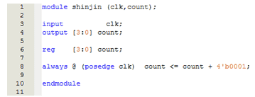
It is designed to count up by “0001” each time the clock rises. To check if it works as required, I created a testbench and simulated it with ModeleSim ®-Altera. Set the clock period to 20 ns. Here are the simulation results.
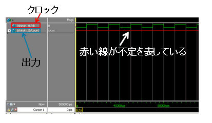
Unfortunately, the output is inconsistent. Why? Let's take another look at the program.

Here, it is written so that "0001" is added to count at the rising edge of the clock. But I noticed one thing here. Since the original value of count is not fixed at the first rise of the clock, it may not be possible to add “0001” and it is indefinite. Yes, just set the initial value for count .
So, I tried rewriting the program as follows.
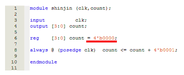
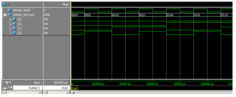
I rewrote the part underlined in red on the 6th line. We defined the initial value for count in this description. And here are the simulation results. This time, I was able to observe how the output counted up properly.
Altera® CPLDs/FPGAs are designed so that the initial value of registers is "0" after startup. Furthermore, for memory blocks implemented as RAM, the initial value will be "0" unless an initial value is defined in a file such as .mif or .hex during the logic design phase (defining an initial value is essential for memory blocks implemented as ROM).
Note: Initial values for registers and memory may vary by device family.
Therefore, when performing logic synthesis and place/route using Quartus® Prime development software, there is no problem as it does not affect the operation of the device even if initial values are not specified.
However, when performing a simulation, the waveform may not come out well unless the initial value is defined as necessary.
Therefore, I realized that it is important to make sure that the initial values are defined before running the simulation.