- Semiconductor BusinessHOME
- Products and Services of Macnica,Inc.
-
technical information

-
Events and Seminars
- Handling Manufacturer
- Support
- Inquiry
- Click here to purchase products
- Semiconductor business e-mail magazine registration
![]()
![]() Narrow down by specifying conditions
Narrow down by specifying conditions
現在2183件がヒットしています。check
Digital isolator and photocoupler technology
Characteristics upgrade by replacing photocouplers
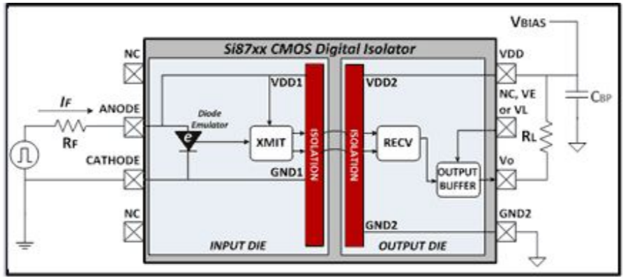
Until now, there were no pin-compatible or package-compatible products that could be mounted on photocouplers. However, CMOS digital isolators Si87xx are direct replacements for optocouplers without changing the PCB pattern, greatly improving performance and reliability. The input side of the Si87xx draws power from the anode input. The output side supplies power from the power supply terminal and can input up to 30Vdc, and is compatible with a general 8-pin photocoupler circuit.
The Si87xx input side die contains elements for diode emulators, high frequency transmitters, and galvanic isolation.
The diode emulator has two functions.
・It mimics the behavior of LEDs and ensures compatibility with existing optocoupler input circuits.
・The internal high-frequency transmitter operates when the anode current is above the threshold.
As the internal transmitter moves, it sends a high-frequency carrier signal across the isolation barrier to the receiver. The receiver receives this, and the output driver is forced low when there is more than a certain amount of energy in a certain band. Conversely, when the input current is below the threshold, the transmitter is disabled, the receiver is not turned on, the output MOS is off, and the output pin goes Hi with a pull-up resistor. This simple structure has many advantages over optocouplers.
Advantages of CMOS digital isolator Si87xx over optocouplers
- Optocoupler and pin compatible, allowing upgrades without PCB changes
- High performance and reliability with patented CMOS isolation technology
- High isolation rating: UL1577 compliant (3.75kVrms and 5.0kVrms for 1 minute) and IEC60065 compliant (10kVpk surge withstand)
- High Speed: 60ns Propagation Delay, 20ns PWD (Pulse Width Distortion) with 1Mbps or 15Mbps Versions
- High CMTI: 35 kV/µS (A grade), 50 kV/µS (B grade) (2x to 3x lower internal parasitic coupling than optocouplers)
- Accurate Input Current Threshold with Low Variation: 2.2mA (A Grade) and 3.5mA (B Grade)
- There is no need to consider CTR (Current Transfer Ratio), which is important for aging deterioration and variation in photocoupler design.
- low temperature fluctuations
- Wide operating temperature range (–40°C to +125°C)
- Reliable: TDDB (Time-Dependent Dielectric Breakdown) > 60 years under worst-case voltage and temperature conditions
Summary of remediation measures for the problem
| problem | photo coupler | Si87xx LED Input Digital Isolator | Si86xx Digital Isolator |
| CMTI Improvement: Wrong Turn-ON | Uses high-threshold optocouplers |
Higher threshold voltage using Si87xx(B) versions |
no problem |
| Adding a clamp diode or switch | Decrease RF (increase current) | ||
| Decrease input limiting resistance RF (increase current) | Delete CL | ||
| Increase the output load capacitance CL value (current increase) | |||
| Decrease output pull-up resistor RL value (increase current) | |||
| CMTI Improvement: False Turn-OFF | Decrease input limiting resistance RF (increase current) | Use version Si87xx(B) with high Input Current Threshold value | no problem |
| Decrease output pull-up resistor RL value (increase current) | Decrease input limiting resistance RF (increase current) | ||
| Increase output pull-up resistor RL value | |||
| Decrease in tPHL | Decrease input limiting resistance RF (increase current) | no problem | no problem |
| Increase output pull-up resistor RL value | |||
| Decrease the value of output load capacitance CL | |||
| Add a peaking capacitor in parallel with the input limiting resistor RF | |||
| Decrease in tPLH | Increase output pull-up resistor RL value | Decrease input limiting resistance RF (increase current) | no problem |
| Decrease the value of output load capacitance CL | Delete output load capacitance CL | ||
| Add a peaking capacitor in parallel with the input limiting resistor RF | no problem | ||
| Dealing with CTR variability | Decrease input limiting resistance RF (increase current) | no problem | no problem |
| Addressing the Aging Effects of LEDs | Decrease input limiting resistance RF (increase current) | no problem | no problem |
result
Digital isolators are a great addition to power system designs. With improved performance, reliability and ease of use, it is ideal for system component installations and new designs.
Isolator product page
Here is a digital isolator product page with useful features.
Inquiry
If you have any questions regarding this article, please contact us below.
To Sky Works Manufacturer Information Top
If you want to return to Skyworks' manufacturer information top page, please click below.