- Semiconductor BusinessHOME
- Products and Services of Macnica,Inc.
-
technical information

-
Events and Seminars
- Handling Manufacturer
- Support
- Inquiry
- Click here to purchase products
- Semiconductor business e-mail magazine registration
![]()
![]() Narrow down by specifying conditions
Narrow down by specifying conditions
現在2149件がヒットしています。check
System failures are inherent in infrastructure network construction. When a problem occurs, on-site engineers are required to solve it as soon as possible. However, the more complex the configuration, such as a company's core system or a large-scale network, the more difficult it tends to be to isolate the problem.
Measuring instruments for optical communication equipment are generally used to measure the characteristics of optical transceivers, but in some cases, they can also be useful in isolating causes of faults other than optical transceivers. In this article, as an example of troubleshooting a link failure in a network device, we will introduce an example in which we found that both the switch and the optical transceiver are the cause.
Link failure that occurred in the customer's environment
A link failure occurred in a 100G optical communication in a customer's environment. The symptom was that the linkup would succeed or fail depending on the port on the switch.
The situation can be summarized as follows.
・The 100G optical link may or may not link up correctly.
・Difference between linking up and not linking up
- Depends on the model number of the optical transceiver used (the problem does not occur with optical transceiver A, but it may occur with B)
- Depending on the port of the switch to be inserted (there are ports that do not cause problems and ports that are prone to problems)
- Depends on the model of the switch used (some models do not cause problems and others do)
After receiving the information, our technical team visited the customer and confirmed that the phenomenon described by the customer was actually occurring.
Analysis using measuring instruments (1) Monitor control signals
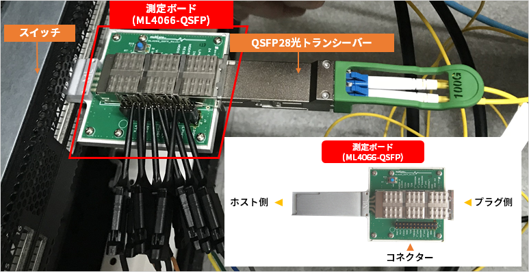
We actually monitored the control signals between the switch and the optical transceiver in several patterns in the customer's environment.
・When the optical link is correctly linked up and when it is not
・When the model number of the optical transceiver or switch model is changed
After monitoring and analyzing the control signals exchanged between the switch and the optical transceiver, we found something interesting.
What we learned by analyzing the control signal between the switch and the optical transceiver
We will check whether there is a difference depending on the pattern.
・Depending on the model number of the optical transceiver used (the problem does not occur with optical transceiver A, but may occur with optical transceiver B)
I checked with several types of optical transceivers, but there was no obvious difference in the control signal even if I changed the optical transceiver.
(It was the same control no matter which one was inserted.)
・Depending on the port of the switch to be inserted (there are ports that do not cause problems and ports that are prone to problems)
There was no obvious difference in the control signal even if the port to be inserted was changed.
(It was the same control regardless of which port it was inserted into.)
・Depending on the model of the switch used (some models do not cause problems and others do)
There was an interesting difference between switches with and without link failures.
What are the differences between switch models?
Analysis of the control signals exchanged between the monitored switch and the optical transceiver revealed some differences.
I noticed this difference.
Exchanging control signals with switches without link failure
- Read Optical Transceiver Register Values from Switch
- Setting the transmission equalizer of the optical transceiver
- Setting the receive emphasis of the optical transceiver
Exchanging control signals with a switch that has a link failure
- Read Optical Transceiver Register Values from Switch
- Setting the transmission equalizer of the optical transceiver
- Setting the receive emphasis of the optical transceiver
- Set the received amplitude to the maximum amplitude passed from the optical transceiver to the switch
The fourth, "Set the received amplitude to the maximum amplitude", is to set the amplitude of the electrical signal passed from the optical transceiver to the switch to the maximum value within the settable range.
I made a hypothesis
Fault-prone switches are configured to maximize the received amplitude of the electrical signal that passes from the optical transceiver to the switch.
Based on the results of this analysis, we hypothesized that link failures are more likely to occur when the received amplitude is small.
Next, we will verify whether this hypothesis is correct by borrowing an optical transceiver from the customer.
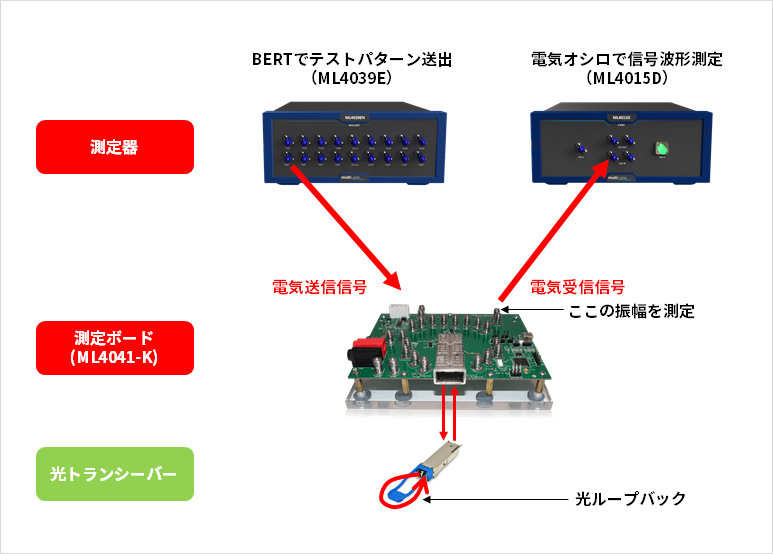
Analysis using a measuring instrument (2) Measure received amplitude
The received optical signal is converted into an electrical signal in the optical transceiver and passed to the switch as an electrical signal. The received amplitude of the electrical signal passed from this optical transceiver to the switch was measured using optical transceivers of different model numbers.
・Optical transceiver A: A model number that does not cause link problems
・Optical transceiver B: A model number that is prone to link problems
As a result, we found that the reception amplitude of optical transceiver B, which is prone to link problems, is smaller than that of optical transceiver A, which does not cause problems. * Although it is smaller than the transceiver A, it is included in the transceiver standard.
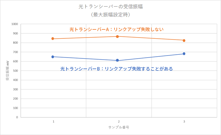
The graph is the result of the measurement. We prepared three transceivers A and B each and measured them.
Orange: Optical Transceiver A with no link issues
Blue: Optical transceiver B prone to link problems
What we can see from this graph is that the received amplitude of the problematic transceiver B is small compared to the received amplitude of the transceiver A.
Based on this result, we reported to the customer that "this switch requires an optical transceiver with a relatively large reception amplitude" and introduced an optical transceiver with a large reception amplitude. I've heard of no link failure issues after that.
What we learned from this analysis
This is what I found in my analysis.
・We analyzed the control signal between the switch and the optical transceiver and hypothesized the cause.
From the control signal, it was found that the received electrical amplitude of the optical transceiver was set to maximum.
• Measured several optical transceivers to support the hypothesis.
We have determined that the received electrical amplitude of the problematic optical transceiver is relatively small.
We found that the received amplitude was relatively small for transceivers with link-up failures, supporting our hypothesis. From this, it can be said that the reception electrical amplitude of an optical transceiver varies between large and small amplitudes even within the range of the standard, and depending on the switch, only large signals can be received normally.
Leave the interoperability test to Macnica.
As in this example, there is a possibility that even a switch and an optical transceiver that can be connected without problems according to the standards will be compatible. In other words, it is important to conduct communication tests as much as possible in advance when configuring optical communication equipment.
Macnica 's technical team has accumulated a wealth of knowledge from past support experience and conducts interoperability tests and troubleshooting between each component using specialized verification machines/measuring instruments. If you are interested, please contact us below.
In Part 2, we will introduce the measuring instruments used in this analysis in detail.

Click here for the product page of the MultiLane instrument used in the analysis of this article
Contact Us