- Semiconductor BusinessHOME
- Products and Services of Macnica,Inc.
-
technical information

-
Events and Seminars
- Handling Manufacturer
- Support
- Inquiry
- Click here to purchase products
- Semiconductor business e-mail magazine registration
![]()
![]() Narrow down by specifying conditions
Narrow down by specifying conditions
現在2191件がヒットしています。check

phase comparator
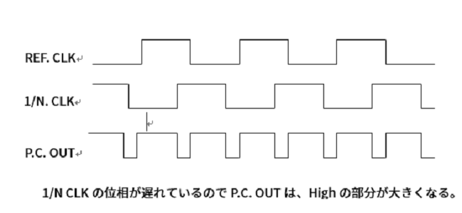
The phase comparator detects the phase lead/delay of the VCO output by comparing the input REFCLK and the phase after dividing the VCO output by 1/N. Figure 3 shows that the VCO output is out of phase with REFCLK. Fig. 1 uses a triangular wave phase detection method, which can be easily configured with EOR or the like. You can also use JK FF, RS FF to configure in Logic.
A charge pump is used together with the phase comparator, and depending on the result of the phase comparison, the capacitor is charged when the phase is delayed and discharged when the phase is advanced, and the phase comparison information is converted into a voltage. In wireless communication, there are cases where only frequency synchronization is performed without phase comparison (Frequency Locked Loop), and the configuration varies depending on the intended use.
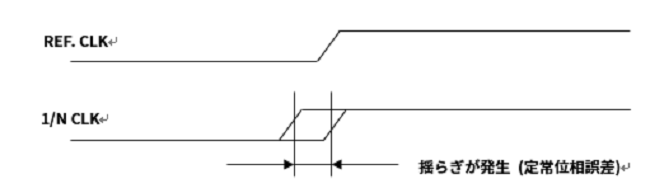
For Analog PLL, selection of phase comparison frequency is also an important factor in PLL design. If the comparison frequency is low, the cycle to update the phase comparison information will become longer, affecting the pull-in time of the PLL. In addition, the longer the update period, the larger the steady-state phase error of the PLL itself (an analog PLL is not perfectly phase-synchronized and has a certain amount of phase error).
Next time, I will describe the Low Pass Filter that smoothes the output of the phase comparator.
Inquiry
If you have any questions regarding this article, please use the button below.
To Microchip manufacturer information Top
If you want to return to Microchip manufacturer information top page, please click below.