
![]()
![]() Narrow down by specifying conditions
Narrow down by specifying conditions
現在1888件がヒットしています。check
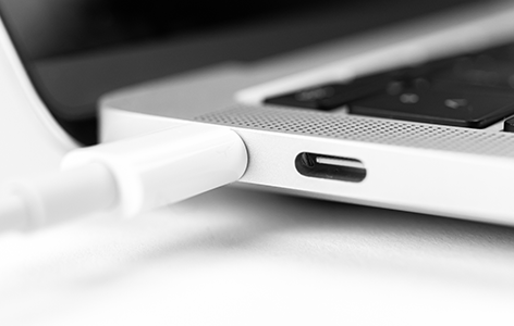
USB Type-C is now widely used, and is being installed in a wide variety of products such as smartphones, digital cameras, speakers, and laptops.
When it comes to adopting our products for our own products, there are probably more engineers who say, "I don't know the points of selecting parts" or "I want to know which manufacturer has a lineup."

This time, regarding USB Type-C, we will introduce the differences from conventional standards, typical charging architectures and issues, how to choose a solution that matches your application, and Analog Devices' solution lineup. Please refer to it.
Reviewing USB Type-C-What is the difference from the conventional standard? ~
USB is defined as the "USB Base Standard (1.1, 2.0, 3.1)" as a basic standard.
- "Type-C Connector"
- "Battery Charging (BC) 1.2"
- "USB Power Delivery (USB PD) 3.1"
specifications are stipulated. Check out the difference between USB Type-C charging and the legacy USB standard.
<Difference between USB Type-C and conventional standards>
|
Conventional USB charging (Ex. Type-A, Micro-B) |
USB Type-C charging |
|
| image |
|
|
| connector | Different shapes for source and sink | Same source and sink shape |
| 4-pin or 5-pin connector | 24 pin connector | |
| front and back | reversible | |
| current voltage |
・Voltage: Almost always 5V ・Current: 1.5A maximum ・Power supply: Maximum 7.5W * Supports fast charging with BC1.2 |
It depends on whether it is Type-C standard or USB PD compatible |
|
<USB Type-C standard> ・Voltage: 5V ・Current: 3A maximum ・Power supply: Max. 15W |
||
|
<USB PD standard> ・Voltage: 5-20V ・Current: 5A maximum ・Power supply: Max. 100W |
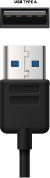
Differences between USB Type-C and conventional standards (1) Connector
The conventional USB standard has various types of connectors, and different shapes were used at both ends, such as Type-A for the source (power supply side) and Micro-B for the sink (charging side).
USB Type-C uses the same 24-pin connector for source and sink. The pin arrangement of the plug (male) and receptacle (female) has been devised, and it has a reversible structure in which the same type of pin can be inserted even if the front and back are reversed.
Differences between USB Type-C and conventional standards (2) Voltage and current
The conventional USB standard only provides a maximum power supply of 7.5W (5V/1.5A), so charging was limited to small devices such as smartphones.
USB Type-C supports power supply of up to 15W (5V/3A) as a standard, and the extended standard USB PD allows power supply of up to 100W (20V/5A). Therefore, it can now be used in a wide range of devices such as monitors and notebook computers.
Now, while USB Type-C is more convenient than previous standards, the charging architecture has become more complex.
Next, we will introduce the USB Type-C charging architecture and issues that designers should know about.
USB Type-C charging architecture and implementation challenges
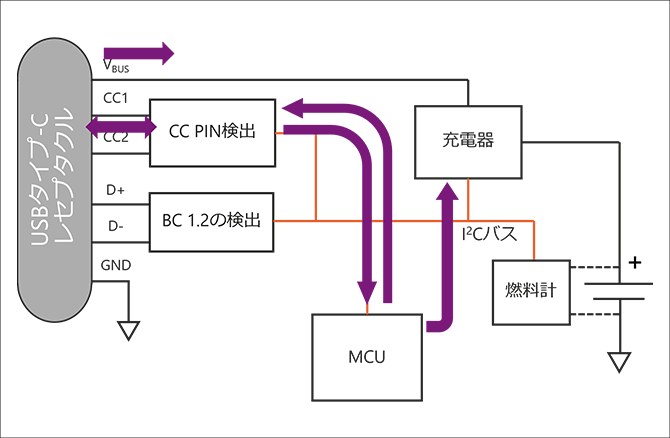
First, a block diagram of the USB Type-C charging architecture is presented. The main blocks are BC1.2 detection, CC pin detection, MCU, charger and fuel gauge.
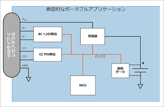
What kind of process do you actually need? Let's use arrows to represent the flow.
[Conventional BC1.2 specifications]
Detects BC1.2 via signal lines D+ and D-, determines port compatibility, and sets the charger with the MCU.
・ MCU polls for BC 1.2 detection
• The BC 1.2 detection block identifies the type of port (DCP, CDP or SDP).
・ MCU reads BC 1.2 port type
・ MCU configures and enables charger
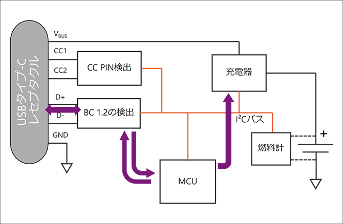
[USB Type-C standard]
USB Type-C detects the newly added CC pin to determine the orientation of the plug, the identification of the source and sink, the corresponding voltage and current, etc.
・ MCU polls CC detection block for cable connection
・ CC Detection identifies cable orientation and power current capability
・ MCU reads sourcing current capability
・ MCU configures and enables charger
[When compatible with USB PD]
To support USD PD, PD negotiation is required after standards negotiation is completed.
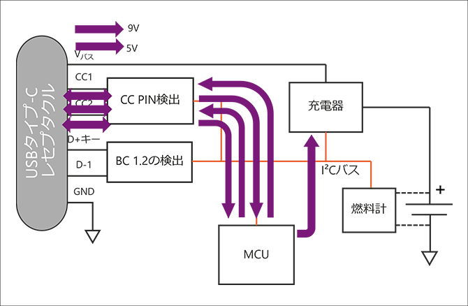
・ PD negotiation is performed after standard CC detection
・ CC Detection requires PD source functionality
• The source advertises a Power Delivery Object (PDO).
・ MCU reads PDO and selects
・ Check PDO selection with CC detection block
-PD source enables new VBUS level
・ MCU configures and enables charger
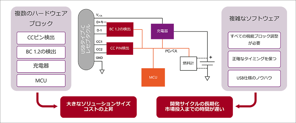
As such, the USB Type-C charging architecture has become more complicated than before. The challenges can be summarized as follows.
<Issues in implementing USB Type-C>
Issue (1) Increase in size and cost due to increase in hardware blocks
More hardware blocks are required, leading to larger solution sizes and higher costs.
Issue 2: Prolonged development and delayed market introduction due to the increasing complexity of software control
Control of each block, adjustment of communication timing, and USB specification know-how are required, making software control more difficult.
This leads to longer development cycles and delays in market launch.
To overcome these challenges, it is important to choose the right charging solution for each USB Type-C-equipped application.
How to choose the best solution for each application
So what should you look for in choosing the right USB Type-C charging solution for your application?
A powerful method is to consider the following two criteria.
<Criteria for selecting charging solutions>
Selection Criteria (1) Desired Power and Flexibility
One perspective is to choose based on the power and flexibility you need. Please refer to the diagram below.
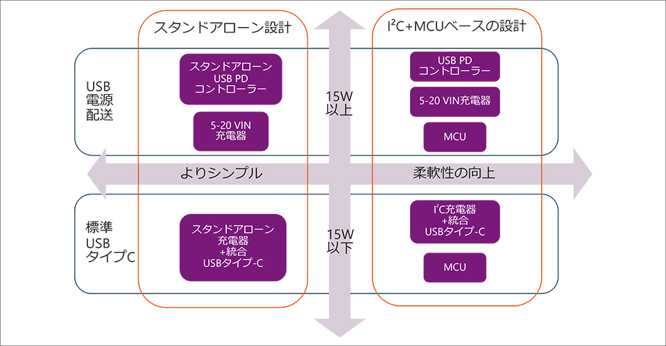
The vertical axis represents power. If it is 15W or less, it is compatible with the USB Type-C standard. If it exceeds 15W, USB PD support is required.
The horizontal axis represents design flexibility. The solution you choose depends on whether you want simple configuration or flexibility.
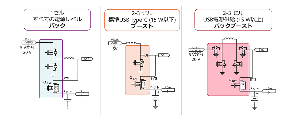
Selection Criteria (2) Topology of Charger by Number of Cells
Another perspective is that the number of cells in the battery necessitates a change in the topology of the charger.
Depending on the number of cells implemented, the voltage across the battery will be different, influencing the choice of buck, boost or buck-boost topology.
Highly Integrated Analog Devices Solutions
What solutions are actually on the market?
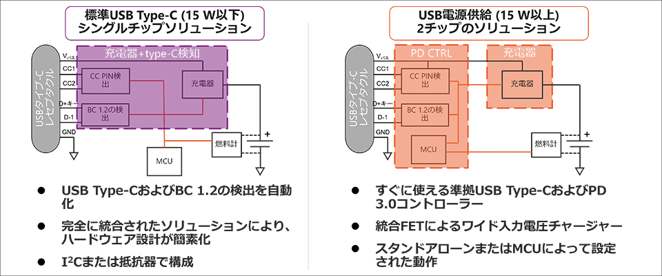
For example, as shown in the figure below, there is a solution that integrates into one chip for 15W or less, and two chips for 15W or more, simplifying the design and shortening the development period.
Analog Devices can offer 1-chip solutions below 15W.
Analog Devices USB Type-C power charging lineup (15W or less)
Now let's take a look at the recommended solutions for each target application from the Analog Devices lineup.
[15W or less] 1-chip stand-alone charger that can be easily mounted
First, 15W Below is the case for a simple configuration application.
<Application example>
·mobile battery
・Charging light
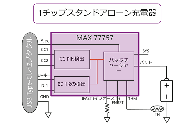
This is the maximum 15W can be charged up to 1 A chip stand-alone charger is best.
No external MCU required and 100 % firmware free. Easy to implement simple charging with no software design required.
advantage
-Automatic detection of Type-C and BC 1.2
- JEITA profile allows safe charging
- All configurations made using resistors or digital input pins
-100% firmware free
Disadvantage
- No on-the-fly parameter changes
-Limited charging voltage and current options
-Type-C port status is barely visible
An example solution is the MAX77757. The feature is that the size can be reduced by about 33 % compared to the equivalent circuit configured with general parts.
In addition, high charging efficiency is also attractive.

[15W or less] 1-chip I²C charger with improved flexibility
Next, the power 15W Below, MCU This is for applications that require control.
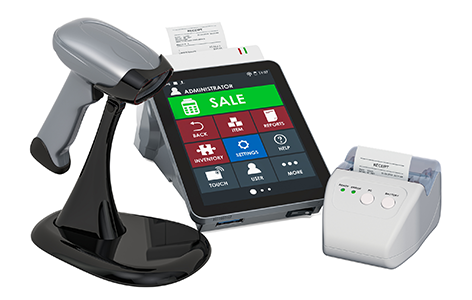
<Application example>
・Payment terminal
・Handy terminal
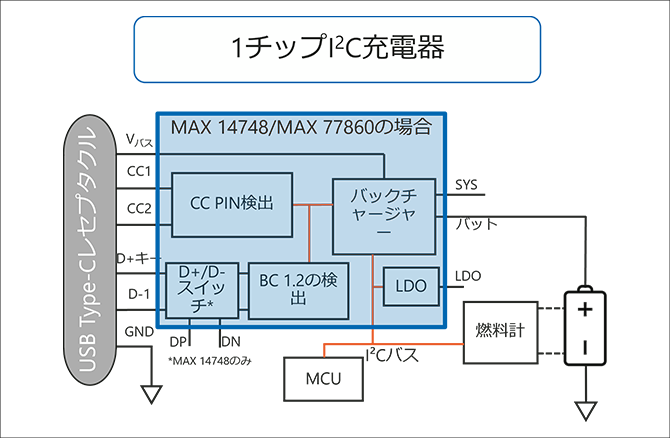
This is the maximum 15W can be charged up to 1 chip I2C Charger is best. I²C by command MCU can be controlled to finely adjust voltage and current.
It is easy to monitor the state of charge and adapt to design changes. (Model number example: MAX14748, MAX77860)
merit
-Automatic detection of Type-C and BC 1.2
- JEITA profile allows safe charging
-Factory ship mode
- Full visibility of Type-C port status
- Override function of setting by I²C
- Provides maximum flexibility
Demerit
- Requires coding of I2C commands
- Relatively more complex in design than standalone solutions
Summary
So far, we have introduced Analog Devices' USB Type-C charging solution.
Compact and highly efficient, it contributes to the speedy introduction of applications to the market.
An evaluation board is available for the solution so customers can easily try it out for themselves.
If you are interested, please feel free to contact us.
Application example
・Smartphones, tablets, laptops
・Portable devices
Click here to purchase products
Click here for manufacturer site/other related links
Inquiry
If you have any questions regarding this article, please contact us below.
Analog Devices Manufacturer Information Top
If you want to return to Analog Devices Manufacturer Information Top, please click the button below.