Broadcast Network Switch Hands-on Seminar Lecture Report Part 2: Learning Network Fundamentals and Characteristics of Broadcast Networks with White Box Switches (Broadcast Network Edition)

Introduction
This article is based on a presentation given at the Broadcast Network Switch Hands-on Seminar held on February 10, 2026.
This guide provides a clear and easy-to-understand explanation of OcNOS, from its basic architecture to its command system, even for beginners.
In Part 1, we systematically introduced the basics of network communication, the operation of the virtual simulator GNS3, and the basic operation of OcNOS, making it easy for even beginners to understand.
In this Part 2, we will explain in detail the features of broadcast networks, such as multicast and PTP.
If you would like to receive the presentation materials, please download them from the link below.
Features of broadcast networks
Overview of broadcasting networks
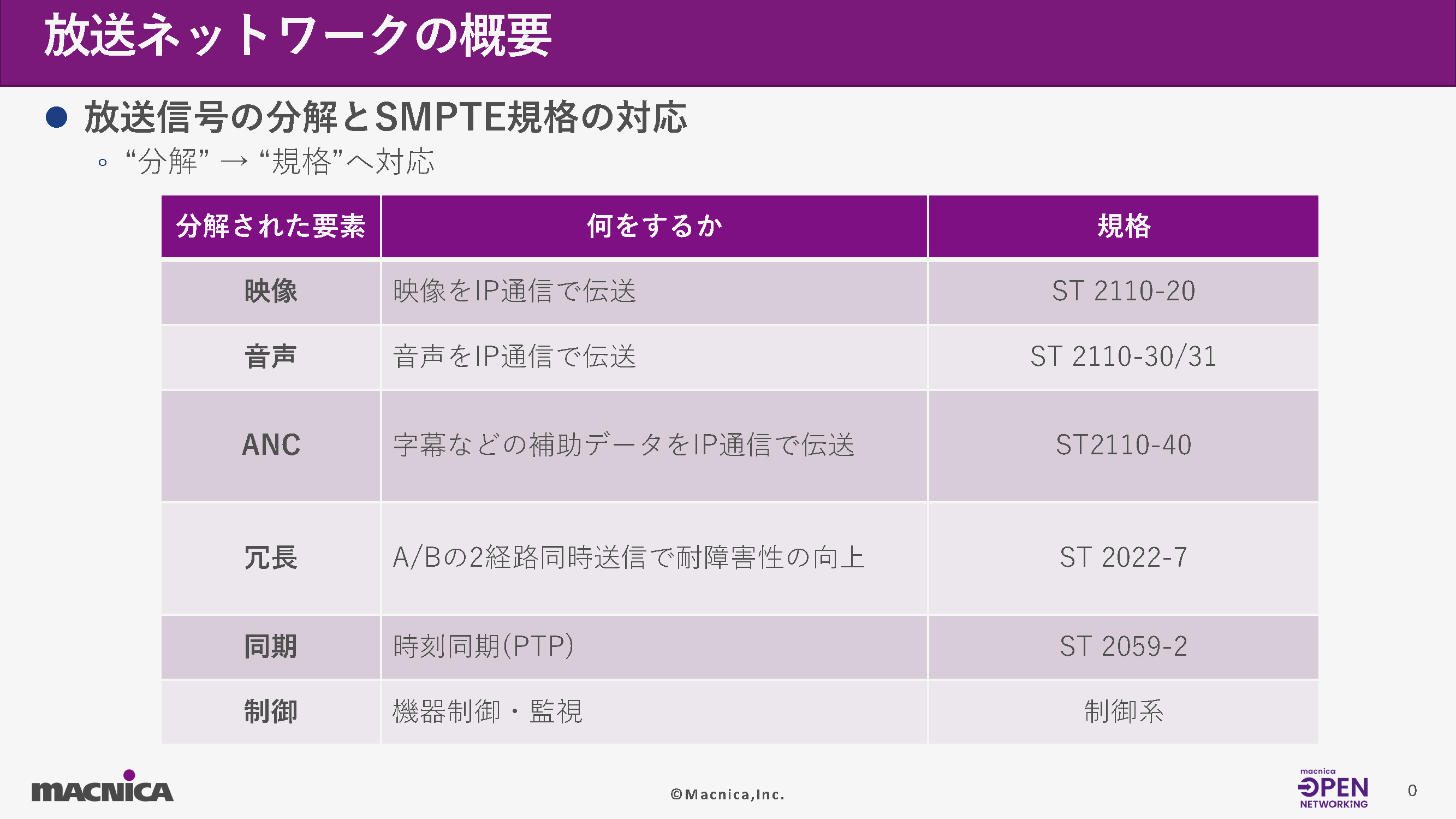
In conventional SDI-based broadcasting systems, video, audio, and ANC signals were multiplexed onto a single cable, and the system was primarily composed of physical wiring.
On the other hand, in IP-based broadcast networks, these signals are broken down into elements such as video (ST 2110-20), audio (ST 2110-30/31), ANC (ST 2110-40), synchronization (ST 2059-2), and redundancy (ST 2022-7), and then reconstructed on the network.
This "decomposition and reconstruction" allows for flexible designs, such as selecting and receiving only the necessary streams, or separating the control system from the media system.
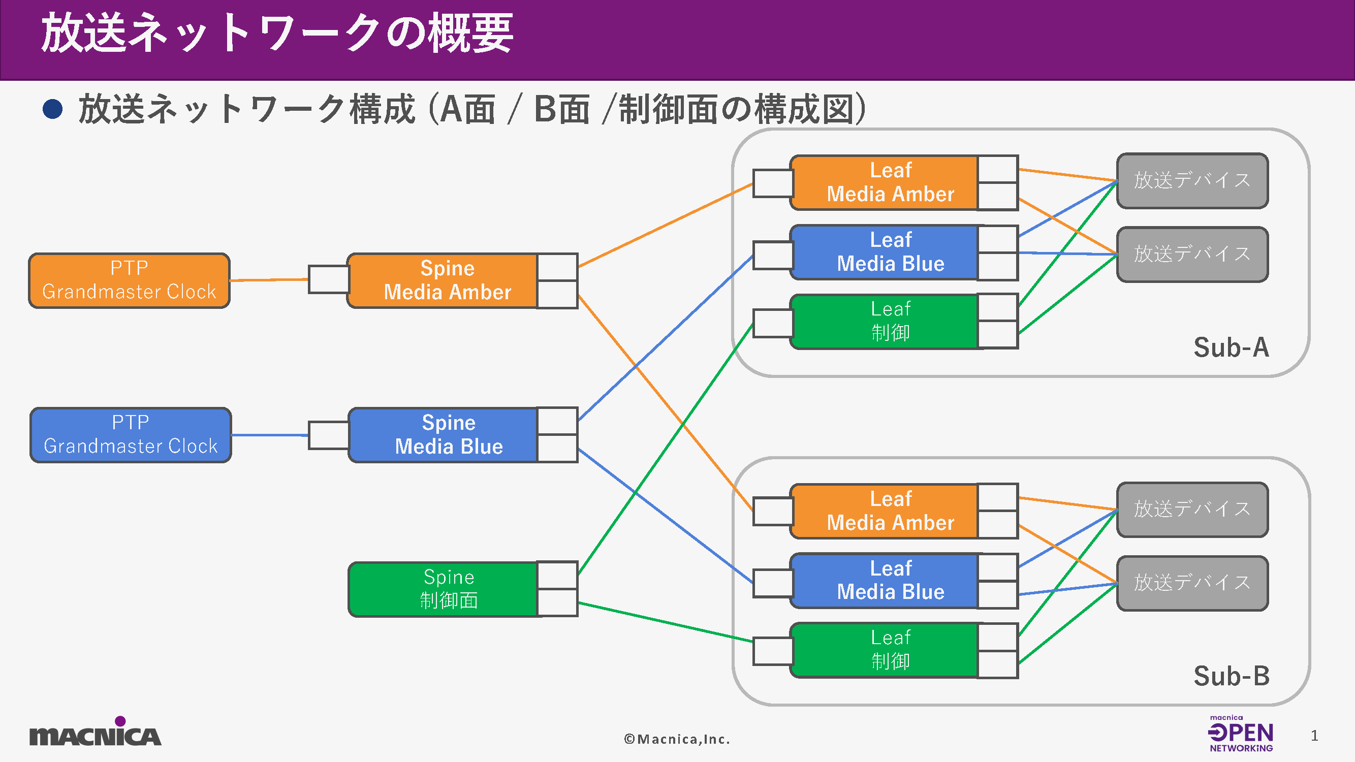
Furthermore, broadcast networks are generally composed of three systems: A-side (Amber), B-side (Blue), and control side (Control). The media system is fully redundant between A and B, while the control system operates as an independent network.
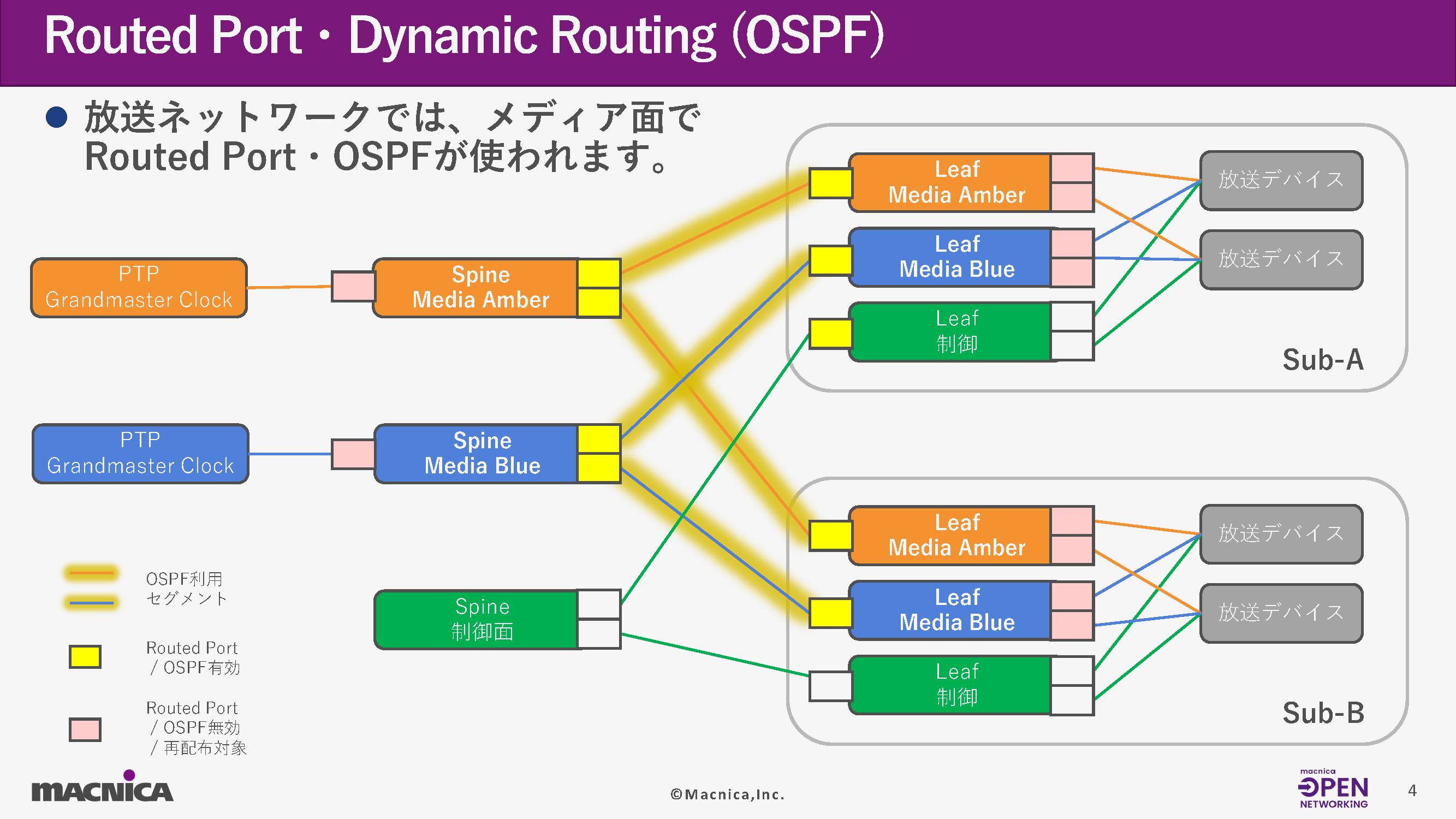
Routed Port・Dynamic Routing (OSPF)
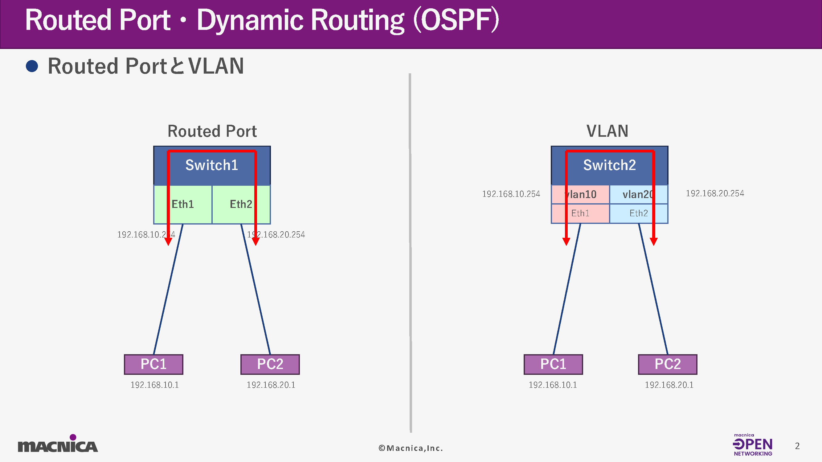
While typical corporate networks use VLANs to accommodate multiple devices on the same segment, broadcast networks almost always employ Routed Ports.
・VLAN method
By configuring IP addresses on the VLAN interface, multiple devices belong to the same L2 segment.
・Routed Port method
Configure IP addresses directly on physical ports and isolate each device at Layer 3.
Regarding route setting
Next, let's talk about setting the route.
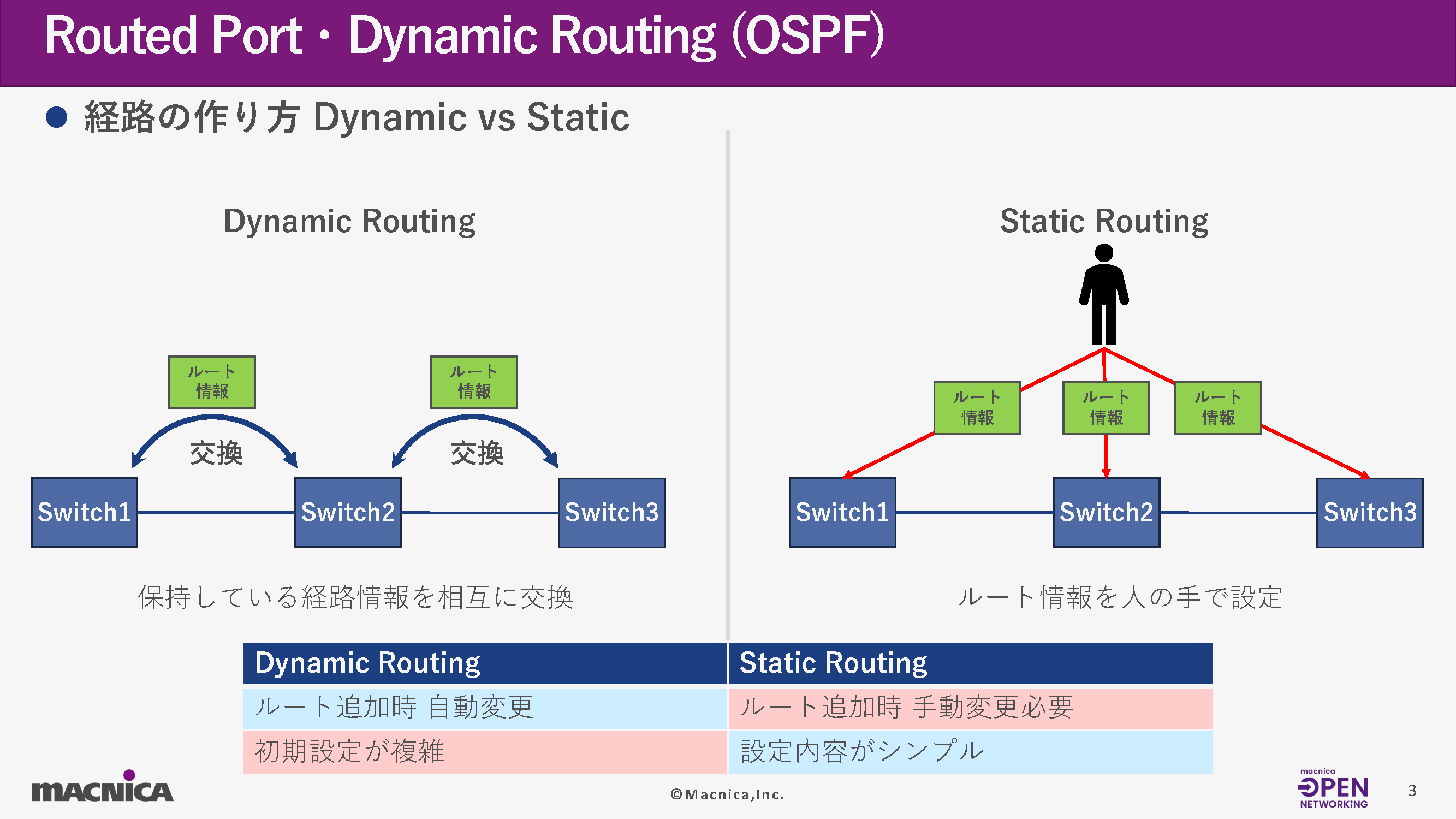
In the media aspects of broadcast networks, dynamic routing using OSPF between the spine and leaf is common.
With static routing, you have to manually add routes to all switches every time you add a device, but by using OSPF, route propagation when a new device is added and automatic failover in the event of a route failure are automated.
In particular, in environments where many devices are connected, such as with the ST2110, autonomous route management through Dynamic Routing offers significant advantages.
The key points of OSPF that broadcast networks should understand are as follows:
Router ID
Identifiers within OSPF
Area
OSPF design unit (Area 0 is common in broadcast networks)
- Segments that establish adjacent paths
Segments that exchange OSPF Hello
redistribute
Configuring a directly connected network to be placed on OSPF
Regarding the uses of OSPF
Next, I will introduce the uses of OSPF that I have explained so far.
In broadcast networks, OSPF communication occurs between Spine and Leaf switches.
In terms of control, you will configure the VLAN settings for the ports.
About the settings and confirmation commands
Finally, let's look at the settings and verification commands.
Routed Port Configuration and Verification Commands
IP address configuration for Routed Port
(config)# interface IFNAME
- Switch to Interface mode
(config-if)# ip address <IP Address>/<Mask>
- <IP Address> specifies the IP address to use.
- <Mask> specifies the mask to use.
OSPF Configuration and Verification Commands
Loopback address configuration
(config)# interface
- Switch to Interface mode (loopback)
(config-if)# ip address <IP Address>/<Mask> secondary
- <IP Address> specifies the IP address to use.
- <Mask> specifies the mask to use.
- Set as secondary address
Set the OSPF router ID.
(config)# router ospf <OSPF Process ID>
- <OSPF Process ID> specifies a number to use within the range of 0-65535.
(config-router)# router-id <Router ID>
- <Router ID> specifies the value to be used in IPv4 address format.
Specify the segment for OSPF communication.
(config-router)# network <Network Address>/<Mask> area <Area ID>
- <Network Address>/<Mask>: Specifies the network address and mask of the segment that will be used for OSPF communication.
- <Area ID>: Specify the area ID of the area to which the target segment belongs (the range of possible values is 0 to 4294967295)
Routing information configuration for redistribution via OSPF
(config-router)# redistribute connected
- connected: Specifies the direct connection path as an OSPF redistribution target.
*For more specific command configuration examples, please refer to the document below.
Reference materials are available here.
Multicast and PTP
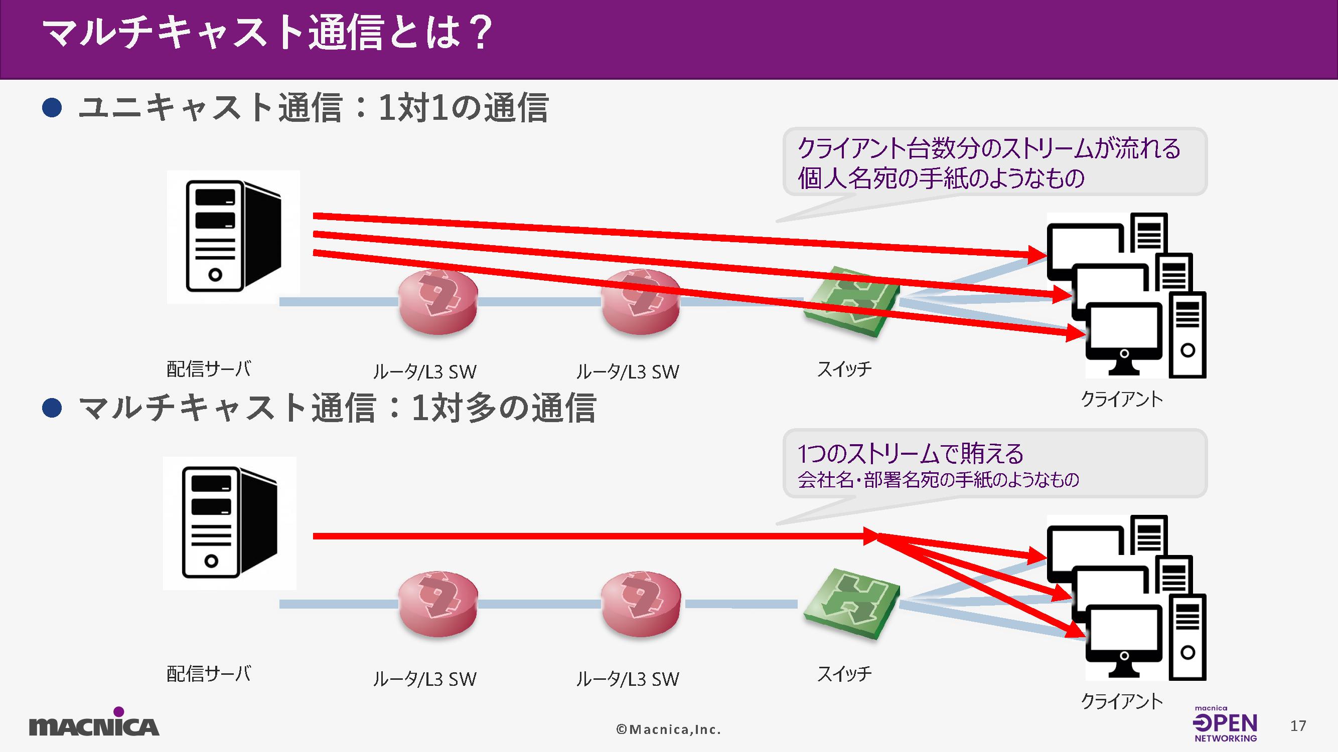
What is multicast communication?
Multicast communication is widely used in broadcasting networks.
While unicast distributes streams by duplicating them in a "one-to-one" manner, multicast is a system based on a "one-to-many" relationship.
This mechanism makes it possible to deliver video to a large number of clients simultaneously while reducing the load on the distribution server.
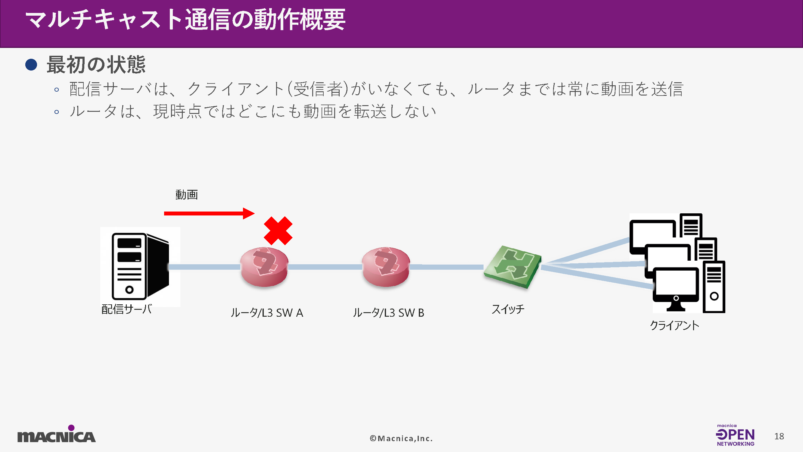
Overview of multicast communication operation
1 Initial state
The streaming server transmits the video stream to the nearest router even before a recipient is detected.
However, the router will not forward the stream anywhere unless requested by the client.
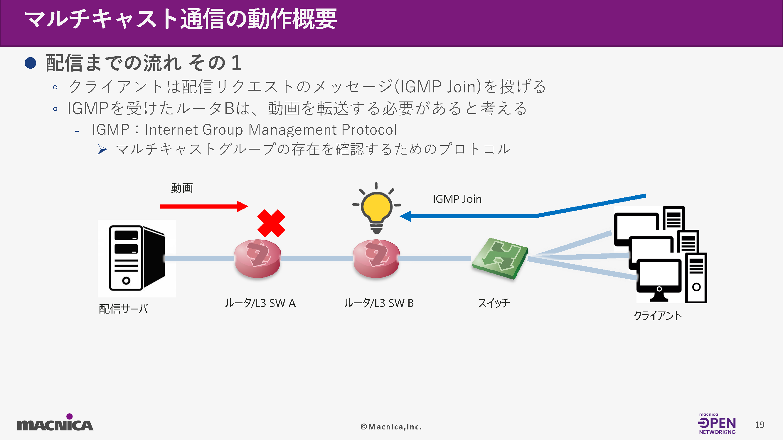
2. Receive request (IGMP Join)
When the client starts viewing, an IGMP Join message is sent.
Upon receiving this, the router determines that "the stream needs to be delivered to this client."
Additionally, IGMP (Internet Group Management Protocol) is a protocol used to notify clients which multicast groups they want to receive.
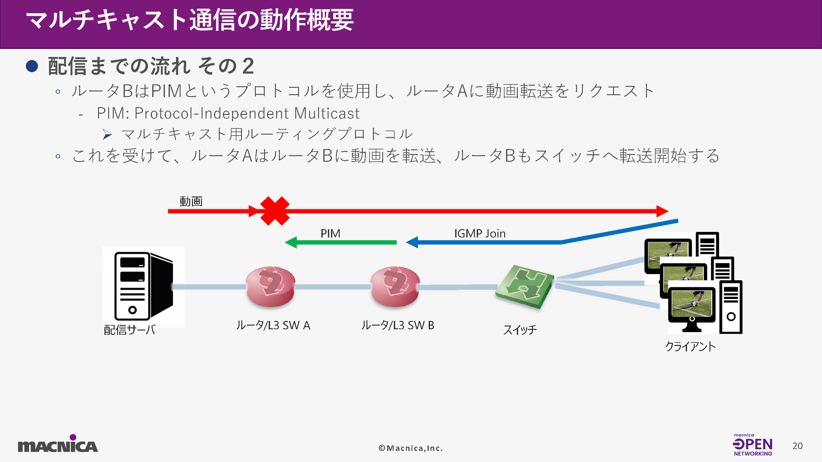
3. Establishing routes between routers (PIM)
The client-side router requests stream forwarding from the upstream router using PIM (Protocol Independent Multicast).
This establishes a multicast path from the distribution server's router to the client's router, and the stream begins to be forwarded.
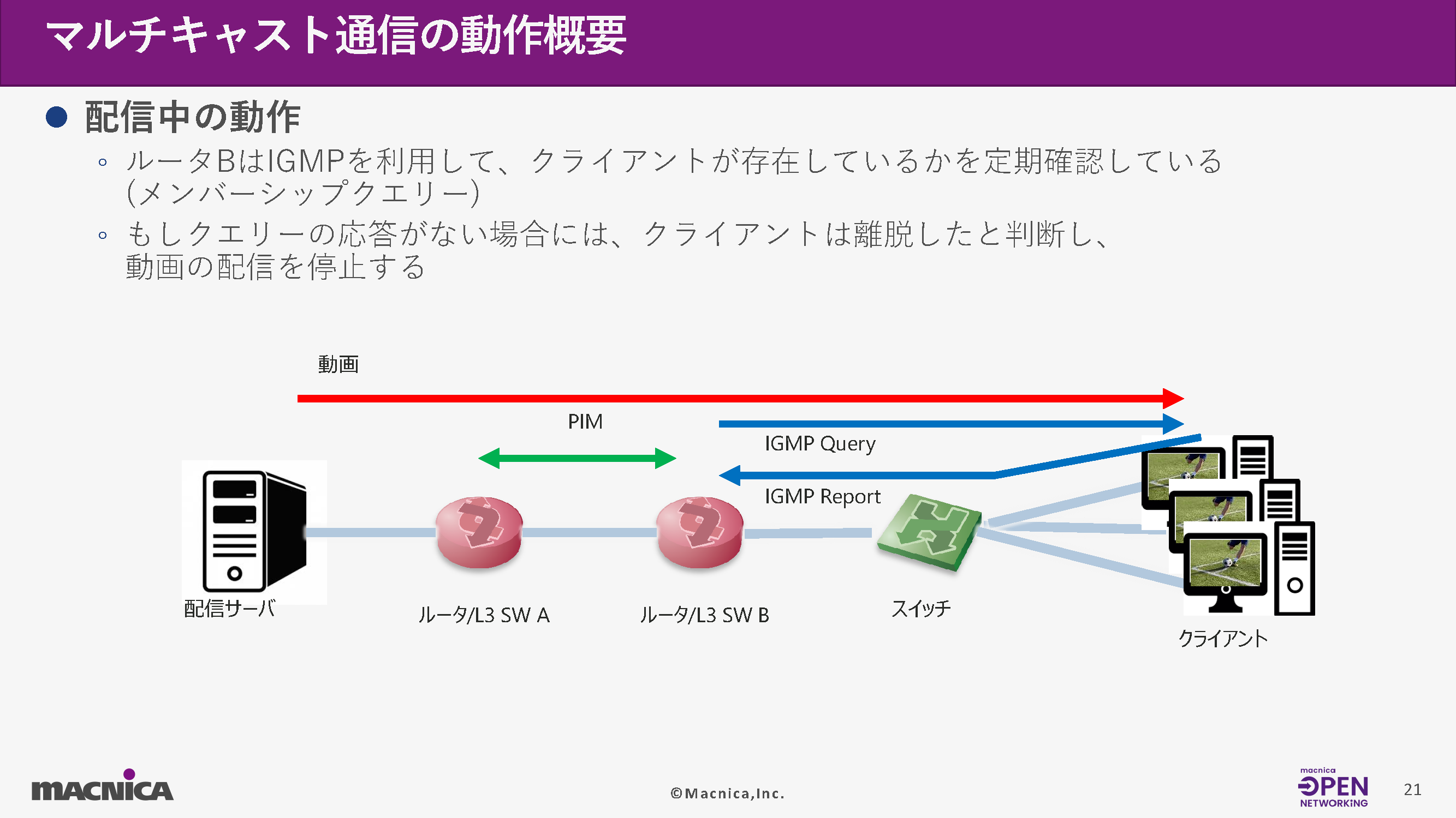
4 Maintaining the distribution
During the broadcast, the router periodically IGMP Membership Query Send a message to check if the client is still watching.
response(IGMP Report) If this is not obtained, the client is considered to have left, and the stream transfer is stopped.
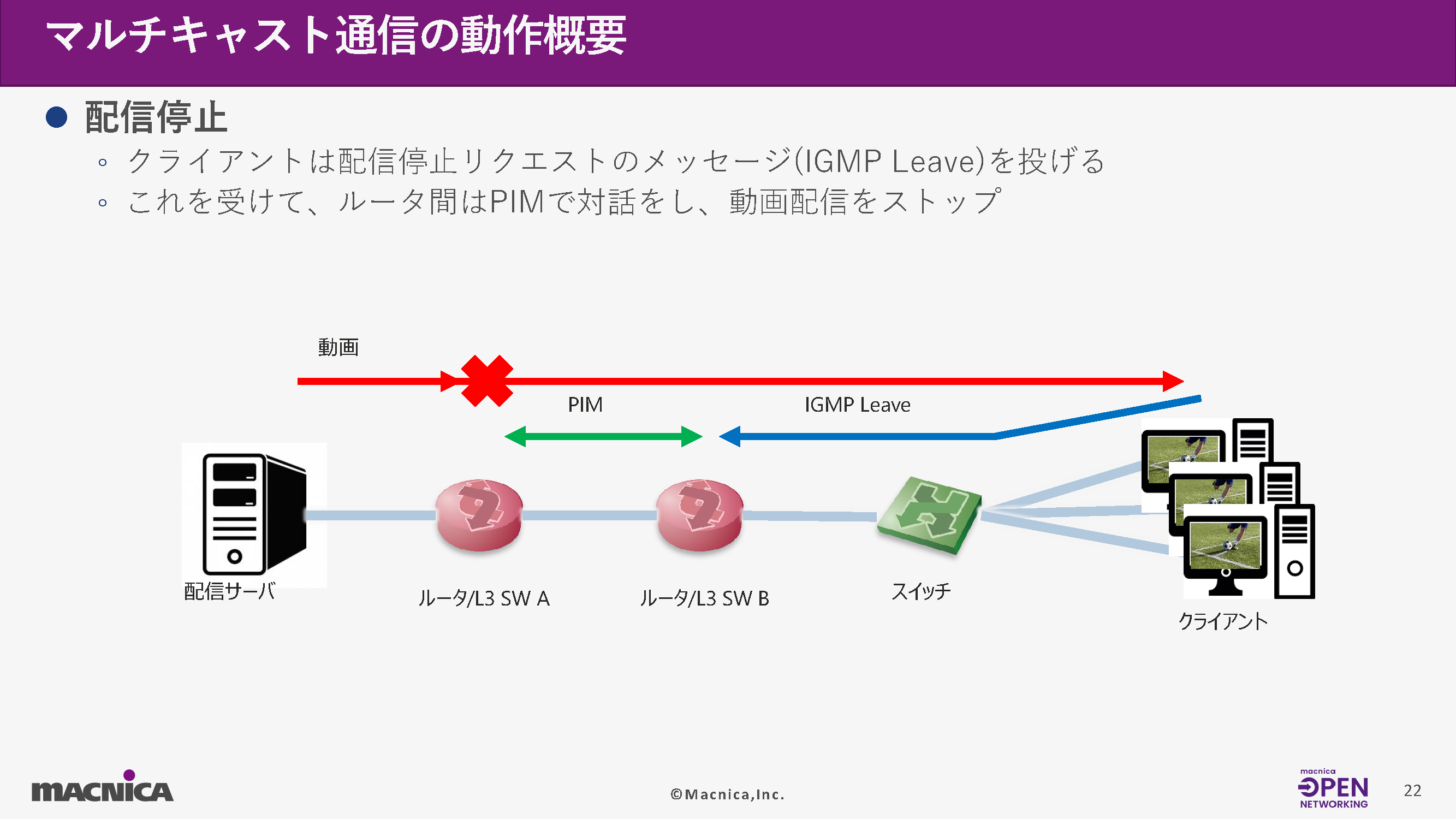
5. End of viewing (IGMP Leave)
When the client finishes watching, an IGMP Leave message is sent.
PIM (Personal Information Management) is used for control between routers, and unnecessary stream forwarding is stopped.
Protocols required for multicast
Multicast distribution involves the coordinated operation of several protocols, including the following:
Routing protocols (OSPF/BGP)
Used to understand the routing information of the entire network and deliver packets to the appropriate destination.
・ IGMP (recipient) → (The first router)
Notifies the client of the multicast groups it wants to receive from.
・ PIM (Between routers)
A routing protocol for establishing multicast routes.
PIM-SM, PIM-SSM There are multiple modes, such as those mentioned above.
<PIM Modes>
・ PIM-SM (Sparse Mode)
IGMPv2 A common method used in combination with other methods
RP(Rendezvous Point) Need
Once a route is established, it automatically switches to the optimal path.
・ PIM-SSM ((Source Specific Multicast)
RP It's unnecessary, and you can use the shortest path from the start.
IGMPv3 Used in combination with
(S,G) Because the source is clearly indicated in the format, it is simpler and more suitable for broadcast use.
Example of a system configuration using IGMP/PIM
Broadcast networks have numerous endpoints, including SDI-IP gateways and IP-based video servers.
These devices are controlled by an external management system (e.g., NMOS IS-04/IS-05), and the network operates autonomously based on IGMP messages from each endpoint.
However, because the network automatically selects the route, there is a challenge in that it is difficult to understand the actual forwarding path.
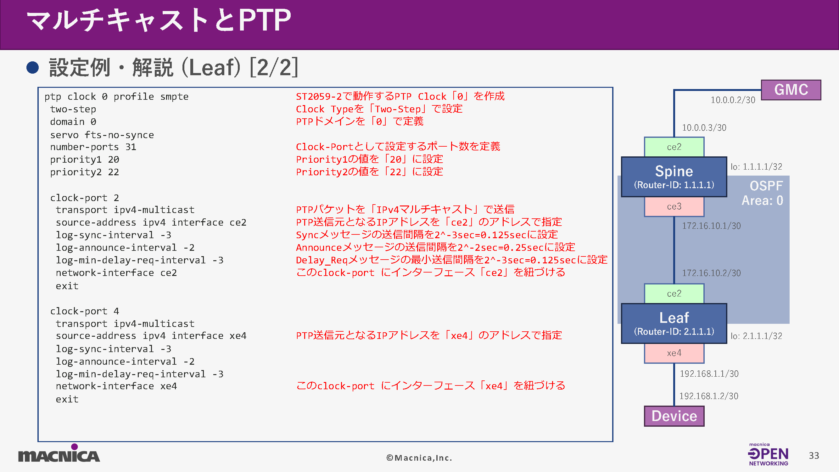
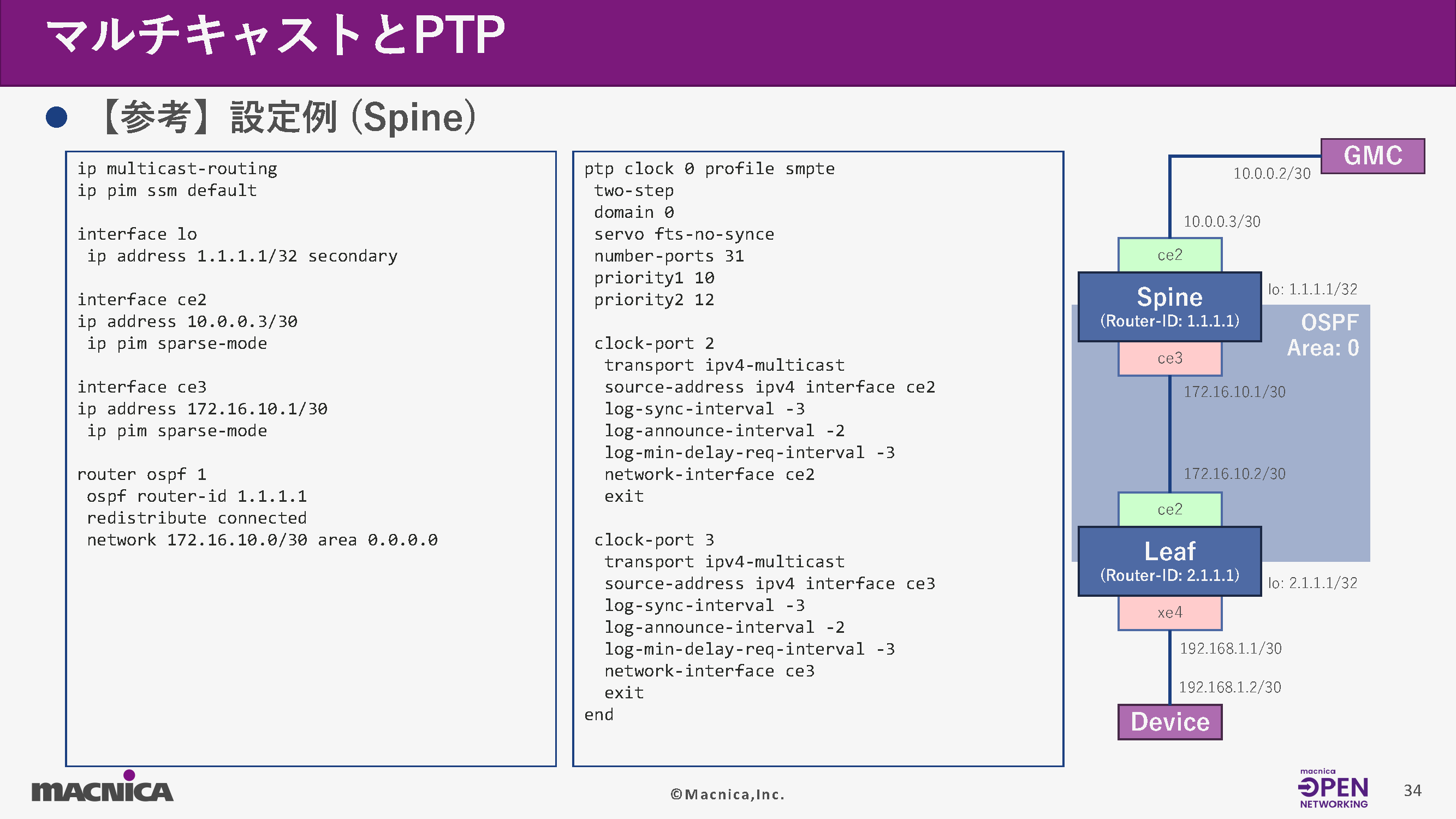
What is PTP?
PTP (Precision Time Protocol) is a high-precision time synchronization protocol based on IEEE 1588.
In broadcast networks, frame-accurate synchronization of video and audio is required, making it an essential technology in SMPTE ST2059 and ST2110.
PTP uses multiple synchronization messages exchanged between the master and slave to distribute accurate time while compensating for network delays.
In broadcast networks, switches also need to be PTP compatible.
A switch can perform one of the following roles:
Ordinary Clock (OC)
Single-port PTP node (e.g., edge device)
• Transparent Clock (TC)
The switch's own delay is added as correction information.
Boundary Clock (BC)
A relay person who receives time from higher levels and distributes it to lower levels.
BC/TC support is particularly important for broadcast applications.
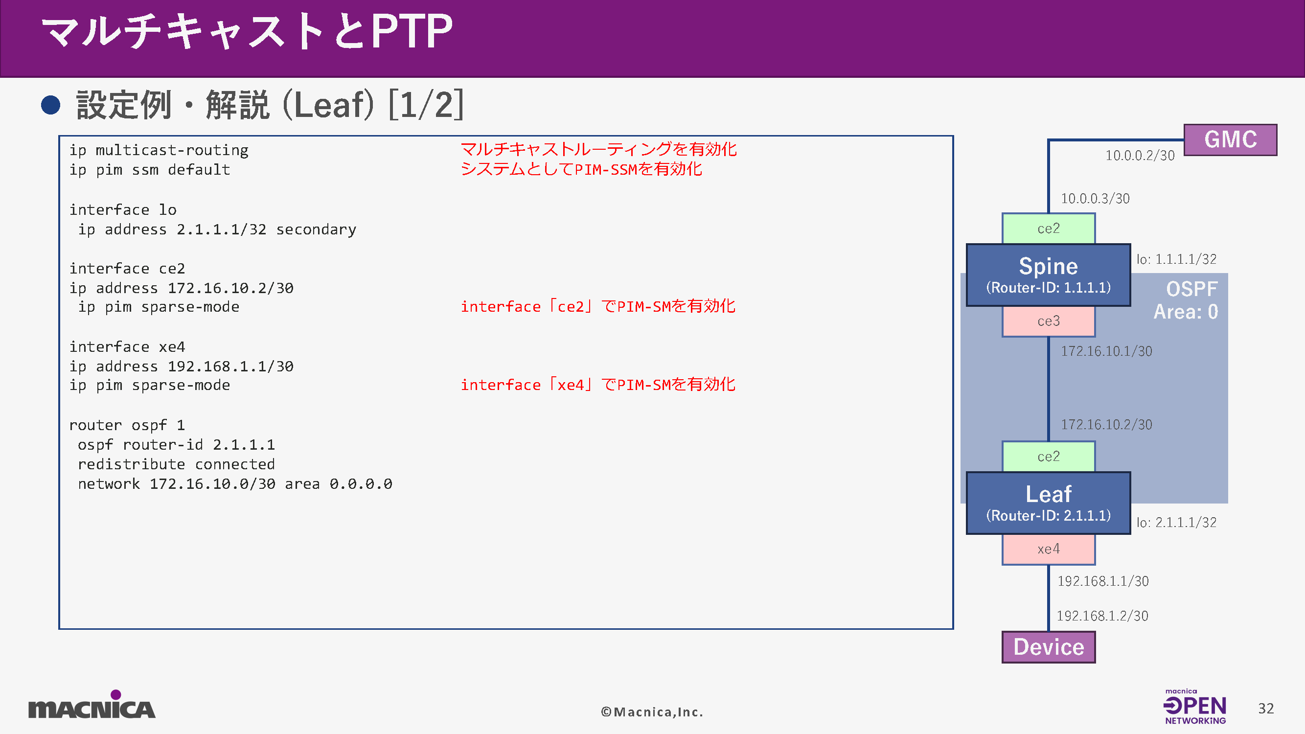
The following is an example of configuration using OcNOS on a Leaf switch.
Summary
This article explained the mechanism of multicast distribution in broadcast networks and time synchronization using PTP.
Both are essential elements in ST2110-based IP broadcasting systems and are key technologies for network design and operation.
Understanding these aspects and being able to design, configure, and verify them appropriately is crucial for the stable operation of an ST2110-based broadcasting system.
We hope this report will be helpful in your network design, troubleshooting, and system updates in your work.
Related information
[Lecture Report Part 1] Broadcast Network Switch Hands-on Seminar: Learning Network Fundamentals and the Characteristics of Broadcast Networks with White Box Switches - Network Fundamentals

[Lecture Report Part 1] SONiC Hands-on Seminar: Learning the Basics of Open Network OS Operations with White Box Switches

SONiC Workshop: Asking a Generative AI About SONiC Source Code
Click here for list of materials
In addition to introducing products handled by Macnica,
We publish materials related to open networking, such as BGP cross network automatic construction files and network operation test evaluation reports.
Click here for details
Click here for the manufacturer's page.

Broadcom, Inc.
We are an industry leader in both semiconductor solutions and infrastructure software, and provide products in a wide range of areas including data centers, networks, broadband, wireless communications, storage, and security.
Edgecore Networks
We continue to be a pioneer in open networking by developing and selling products related to OpenNetworking/white Box switches.

IP Infusion
As a market leader among open networking providers, we provide reliable network solutions to over 600 customers, including carriers, service providers, and data centers.