- Semiconductor BusinessHOME
- Products and Services of Macnica,Inc.
-
technical information

-
Events and Seminars
- Handling Manufacturer
- Support
- Inquiry
- Click here to purchase products
- Semiconductor business e-mail magazine registration
![]()
![]() Narrow down by specifying conditions
Narrow down by specifying conditions
現在2168件がヒットしています。check

After working at a machine manufacturer for three and a half years, working on development work such as housing and mechanism design, I joined Macnica mid-career as an FAE.
Macnica has a large proportion of mid-career employees, so it's very easy to work here and you don't feel alienated at all.
Originally, I studied mechanics at university and had no knowledge of electricity when I joined the company, so I started over from Ohm's law and am currently studying hard.
I had an opportunity to actually design a DC/DC converter under such circumstances, so I hoped it would be helpful for a beginner electrician like myself.
I will introduce the process.
This is the 4th draft, please see the 3rd draft here.
It's finally the final episode!
How much performance can a DC/DC converter made using a discrete board exhibit?
We will introduce the observation results of efficiency, phase margin, and operating waveforms.
Operation waveform measurement
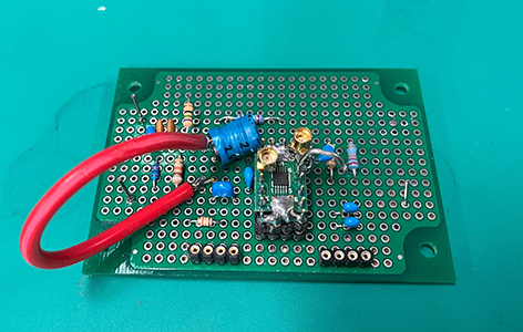
Board used
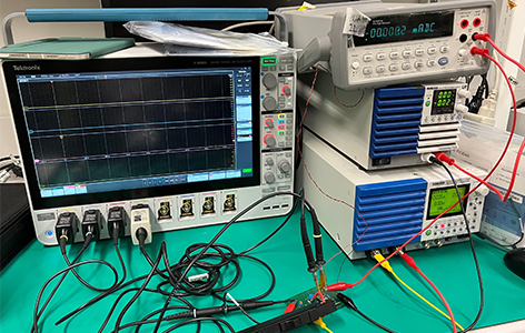
Measurement environment
First, let's observe the operating waveforms.
I think there is a thick red line that stands out on the board, but this is the wiring for measuring the inductor current.
During the initial evaluation, I was asked to observe the inductor current, but I was wondering how. . I was thinking,
The current probe is installed by stripping one leg of the inductor and connecting the other leg with thick wire.
He taught me a technique to create a gap to fit in, and I was able to successfully measure it.
I felt that this area also required measurement know-how. When we receive requests from customers for measurements and analysis, etc.
When I heard that such modifications were made, I thought I should improve my skills. (I can't fail.)

Measurement waveform (input voltage 12V, output voltage 5V, output current 2A)
The last adjustment was worth it, and we can confirm that the SW waveform, inductor current waveform, and output voltage are all operating normally.
Last time, when we measured the SW waveform using the MMCX connector, we observed a small overshoot.
This waveform measures the SW waveform and output voltage waveform using the MMCX connector.
Since the input voltage waveform is taken with a normal probe, there may actually be a little less ripple in the input voltage waveform.
I feel that I have become more aware that the waveform on the oscilloscope is not necessarily the true waveform.
Having learned the importance of measurement points, I decided that the next time I would create a board, I would design it to include an MMCX connector from the beginning.
Efficiency measurement
Next is efficiency measurement.
Efficiency can be calculated using the following formula
Efficiency n = (input voltage x input current) / (output voltage x output current)
Therefore, efficiency can be determined by measuring the input/output voltage and current of the device.
Good efficiency means less loss in devices and circuits and better performance.
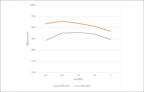
Created efficiency graph
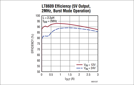
Datasheet efficiency graph
Let's compare the efficiency graph we created with the efficiency graph in the datasheet.
The graph I created has a rough plot interval, so it looks rough, but if you compare it at the efficiency peak (12VIN, 0.8Aout), the board you created is also on a pretty good line.
However, under other conditions, the created board loses. .
The extent to which efficiency can be extracted seems to vary greatly depending on the board design.
This time, since it was made with a universal board, there may be a lot of loss component in the wiring, which may be affecting the efficiency.
Phase margin measurement
Next, we move on to measuring the phase margin.
Simply put, phase margin is an index that indicates the degree of stability of a control system.
If this is too low, FB control will not work properly and the output voltage will oscillate.
In this measurement, the phase margin standard is generally said to be 50° to 60°, so we checked whether this was met.
I would like to check it out.
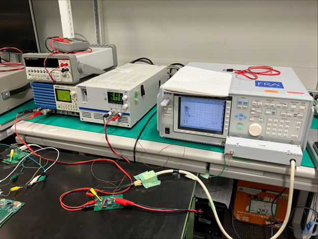
Phase margin measurement equipment
bode plot
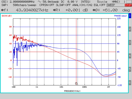
When the measurement is completed, the measurement results and Bode plot will be output.
I would like to list all the conditions, but I don't have enough space, so I have excerpted the results for 12V-1A output.
*Θ:+61.00deg at the top right of the Bode diagram indicates the phase margin at 12V-1A output.
It exceeds the ideal angle of 60°, so it can be said to be stable!
However, there is another indicator called the crossover frequency, and this frequency is the same as the drive frequency.
It is said that it is preferable to adjust it to about 1/10.
This is related to load responsiveness, but I will omit it here.
For more information on phase margin and load response, please see below.
Phase margin measurement service
Verification of the trade-off between DC/DC converter phase margin and load response
At the end
A former mechanical engineer who knew only what he learned about electrical circuits at school
I tried making a DC/DC converter using a universal board. How was it?
Personally, I was very impressed that I was finally able to move the device even though I didn't know what was right and what was left.
Also, unlike with machines, I realized how difficult it is to see defects, so I was able to deeply appreciate the importance of measurement.
This concludes the universal board edition, but next time we will cover the printed circuit board edition.
looking forward to!
Universal board edition article list
■Universal board edition
・ I made a DC/DC converter using a universal board (1)
・ I tried making a DC/DC converter using a universal board (2)
・ I tried making a DC/DC converter using a universal board (3)
・I made a DC/DC converter using a universal board (4)
■Printed circuit board edition
・ Create a power supply with your own printed circuit board! (1)
・ Create a power supply with your own printed circuit board! (2)
・ Create a power supply using a homemade printed circuit board! (3)
・ Create a power supply using a homemade printed circuit board! (4)
・ Create a power supply using a homemade printed circuit board! (5)