- Smart City/Mobility Business HOME
- Search by use case
-
Search by product/service

- event·
seminar -
Case studies and columns
- Inquiry
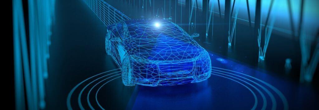
autonomous driving uses various sensors to play the role of human eyes. Among them, the sensor called LiDAR is considered to be the most important for autonomous driving. In this column, we will introduce the basics such as the configuration and performance of LiDAR, as well as the latest functions and in-vehicle requirements.
LiDAR and autonomous driving
Sensor group used for autonomous driving
Various sensors are used for autonomous driving. ADAS (Advanced Driver Assistance System) has been widely used for a long time, but the front radar was first adopted. Since then, various sensors have been put into practical use today, such as stereo cameras, perimeter monitoring radars, and AI-based forward cameras. LiDAR is said to be a key sensor for autonomous driving despite the wide variety of sensors. This is because it is considered indispensable for realizing important functions in autonomous driving such as object recognition and self-localization.
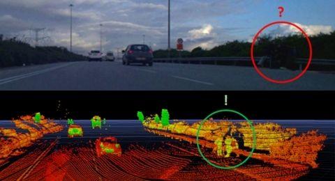
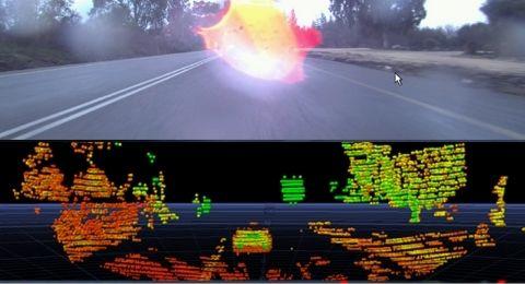
In object recognition, the development of cameras and image recognition has been remarkable, and it is no exaggeration to say that image recognition using deep learning in particular has revolutionized technology. However, even that camera + image recognition cannot measure the exact distance of an object. In addition, when the illuminance of the camera is low, the image is blackened, which hinders object detection. LiDAR, on the other hand, can measure the distance of objects, allowing for more accurate obstacle avoidance. Also, since it fires its own laser, it can see clearly even in the dark. In addition, cameras are easily affected by water droplets on lenses and windows, but LiDAR is less affected unless the laser beam is completely blocked.
Next, with regard to self-position estimation, it is impossible to follow the correct route in autonomous driving without accurately grasping where you are in real time. There are several methods for estimating self-location, such as using GPS (Global Positioning System) signals and using tire rotation speed. Self-localization using this method alone is not practical due to problems such as the size of the device and the GPS signal not being obtained in mountainous areas or tunnels. In addition, the method of calculating the amount of movement based on the number of rotations of the tire is not practical because it requires the input of the starting position, and errors accumulate due to tire slippage and the like. On the other hand, self-location estimation by LiDAR can accurately estimate self-location by comparing a high-detail map and a map acquired by LiDAR.
For this reason, LiDAR can be said to be the core sensor of autonomous driving.
Basics of LiDAR
What is LiDAR
LiDAR is an abbreviation for Light Detection And Ranging, and uses remote sensing technology that uses laser light to detect objects and measure distances to objects. It measures the time it takes for the irradiated laser light to hit the object and bounce back, and measures the distance and direction to the object. In addition, since a laser beam with a high luminous flux density and a short wavelength is used, it is possible to detect positional information and the shape of an object with high accuracy.
autonomous driving, it is being adopted as the role of the “eye” of the machine, and recently, its use is accelerating in fields such as surveying, AR (augmented reality), and security.
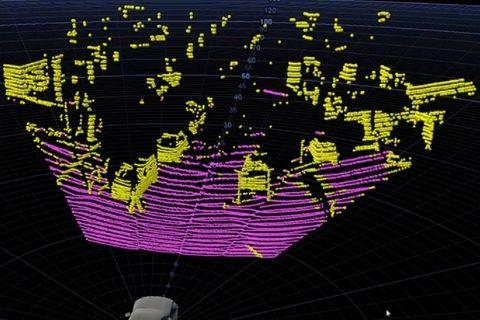
point cloud
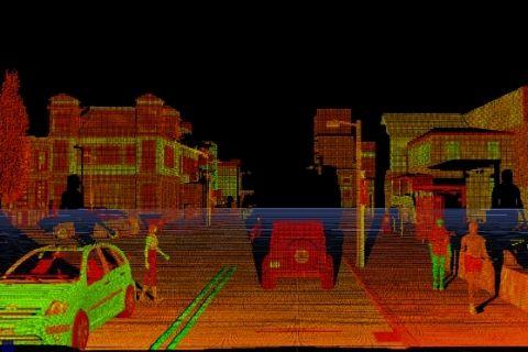
The information obtained with LiDAR is called a point cloud. It's just a collection of dots. When viewed with a viewer, it looks like an image captured by a camera, but it is actually represented by individual dots. I mentioned that LiDAR performs object detection and positioning, but each of these points is displayed on the viewer based on the coordinate data obtained by the positioning, so for example, top view or side view etc. , can change the point of view. Moreover, it is also possible to color-code by distance, color-code by height, etc. from the coordinate information. In addition, many LiDARs also carry reflectance information, so you can color code the point cloud by reflectance. For example, since the reflectance of white lines on asphalt and roads is different, it is possible to detect lanes and arrows of left and right turn lanes.
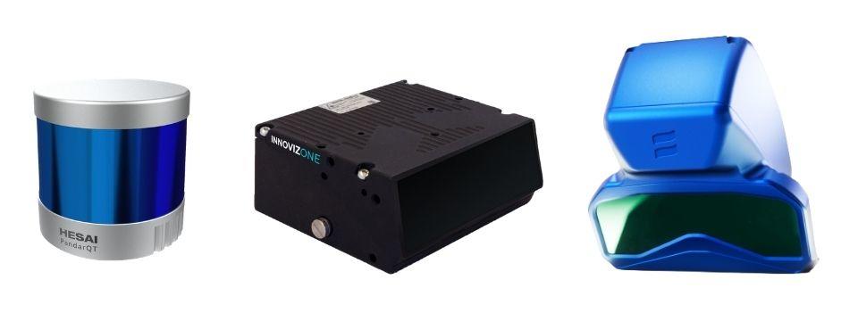
Rotational and solid-state
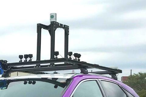
There are various types of LiDAR, but the easiest to understand is whether they are rotating or non-rotating. The rotary type is also called a mechanical type, and is a method in which a module equipped with a large number of lasers is rotated. The non-rotating type is also called a solid-state type, and is a method of scanning by beam steering instead of rotating the laser itself as described above. The rotating type is an excellent method that allows a 360-degree view with a single unit if it is installed at a high position on the roof of the vehicle, but it is not suitable for the design of passenger cars. In addition, it is said that it is not suitable for mass production because of its low resistance to vibration and impact of rotating parts. For this reason, companies are racing to develop solid-state LiDARs.
LiDARの構成要素と性能指標
Laser element and light receiving element
LiDAR lasers use near-infrared rays. Wavelengths such as 905 nm and 1550 nm are common. The former generally uses a silicon semiconductor laser, and the latter generally uses a compound semiconductor laser. Silicon semiconductors are more advantageous in terms of price and power consumption, but the 1550nm band has less impact on the retina, making it easier to increase output. Also, since the output of this wavelength band contained in sunlight is relatively lower than other wavelength bands, it is less susceptible to sunlight.
A photodiode, a SPAD (Single Photon Avalanche Diode), or the like is used as a light receiving element, but since the 905 nm band can be manufactured with a silicon semiconductor, it is inexpensive and consumes little power.
Beam steering method
Beam steering, that is, the scanning method of laser light, varies from company to company. For example, the 2D MEMS (Micro Electro Mechanical Systems) type implements raster scanning by mounting a mirror on a two-axis movable element and reflecting laser light on it. In addition, there are many unique methods of each company, such as a type that rotates a small mirror and a type that scans by refracting a laser beam with a different wavelength that is incident on a prism.
The rotating type is characterized by a wide viewing angle of 270° or 360° in the horizontal direction by rotating the head equipped with multiple lasers. Generally, there are no moving parts in the vertical direction, and the resolution and viewing angle are determined by how the multiple lasers are mounted. For example, if 32 lasers are staggered by 1°, the vertical viewing angle will be 31°. There are many products that make it easier to see.
On the other hand, a number of solid-state type products that are not rotating types have appeared for several years. Among them, the silicon MEMS mirror is a microelectromechanical system integrated by semiconductor microfabrication technology. So-called MEMS LiDAR realizes raster scanning by mounting a mirror on a biaxially movable device called 2D MEMS and reflecting laser light on it. Since MEMS is driven by permanent magnets and electromagnets, frictionless high-speed and high-precision beam steering is possible.
Ranging method
A pulse TOF (Time of Flight) method is generally used as the ranging method. Some manufacturers are trying to adopt the FMCW (Frequency Modulated Continuous Wave) method, but it can be said that the technology is still under development. The pulse TOF method is a method of calculating the distance by emitting a laser at regular intervals and measuring the time it takes for the reflected wave to arrive. On the other hand, the FMCW method, which is commonly used in radar, continuously irradiates while modulating the frequency, and calculates the distance by measuring the time it takes for the reflected wave to arrive. . The major difference from TOF is that the relative velocity to the object can be calculated by measuring the wavelength change of the reflected wave due to the Doppler effect.
signal processor
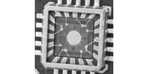
For signal processing, FPGAs (Field-Programmable Gate Arrays) are suitable for high-speed processing of simple calculations. However, general-purpose FPGAs have specifications that are either too much or too little, and prioritizing performance often requires using higher-end models, which are not always the optimal solution in terms of size, cost, and power consumption. Therefore, some manufacturers are developing dedicated ASICs (Application Specific Integrated Circuits) to reduce size and power consumption while maximizing performance. This will likely be key to future miniaturization and performance improvements.
However, in the future, the LiDAR method and signal processing method will become more common, and as LiDAR becomes more popular, package ICs will be released by each processor manufacturer. As a result, it will be possible for anyone to create a radar by integrating an MMIC (Monolithic Microwave Integrated Circuit) and an MPU (Micro-Processing Unit) like the current radar, and further miniaturization and cost reduction will progress. be Such an era may be near.
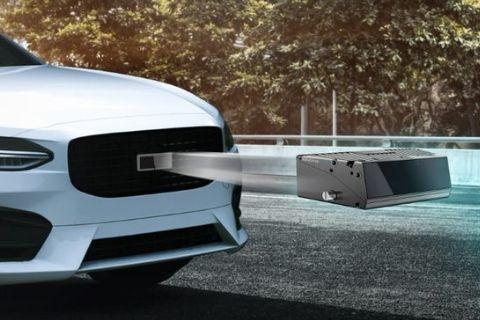
Detection distance
The maximum detection distance is literally how far an object can be seen, and is a very important performance for object detection. To put it a little more technically, it's the maximum distance that the laser light emitted by the LiDAR can be reflected off an object and captured by the receiver. In other words, the performance is affected by the laser beam intensity, the reflectance of the object, the ambient noise, the sensitivity of the light receiving section, and the signal processing performance.
The easiest way to extend the maximum detection distance is to increase the output of the laser, but in order to reduce the effects on the human eye, IEC 60825-1 Class 1 level eye-safety is required. In addition, laser power is limited due to heat generation problems of the device. Increasing the sensitivity of the light-receiving part naturally extends the maximum detection distance, but it also makes it easier to pick up noise. Therefore, the difference in performance will be the optical system in front of the light-receiving part that removes light other than reflected light and the noise filtering in the signal processing part.
Not only the maximum detection distance but also the minimum detection distance is important. For example, when LiDAR is mounted on the grill of a vehicle, the minimum detection distance should be as small as possible to monitor the surroundings of the vehicle. However, it is difficult to achieve both the maximum detection distance and the minimum detection distance.
Field of View (FOV)
The viewing angle is also called FOV (Field of View), and it literally means how much range can be seen. A feature of the rotary type is that a wide viewing angle can be obtained by rotating a head on which multiple lasers are mounted. Solid-state, on the other hand, typically has a narrow viewing angle due to limited beam steering. However, today it has achieved a wide viewing angle of around 120 degrees, such as by incorporating multiple MEMS.
The vertical viewing angle is the number of lasers in the rotating type, and the beam steering angle in the solid-state type is the same as the horizontal viewing angle. This is considered sufficient for automotive applications, but a wider vertical viewing angle would be appreciated for high-mounted security and perimeter monitoring applications for construction machinery.
Frame rate/Period
The frame rate is expressed in fps (frames per second), just like camera images, and indicates how many frames are updated per second. There is also a method of expressing by period [Hz], but both have the same meaning. In recent LiDAR, 10 to 30 fps is common, but considering high-speed movement such as highways, about 30 fps is essential.
An increasing number of manufacturers are adopting variable frame rates by changing the laser firing timing and scan rate. Rotating LiDAR can change the frame rate by changing the angular velocity, but the speed is limited by the weight of the rotating object. In addition, since the centrifugal force also increases, the weight balance becomes severe. On the other hand, with the MEMS method and rotating mirror method, it is easier to increase the frame rate than with the rotating type, but increasing the frame rate also means increasing the processing speed, so it is necessary to strike a balance according to the application.
resolution/resolution
Resolution is also one of the important performance. For example, we all know that the higher the number of pixels in a digital camera, the higher the image quality. Even in LiDAR, the higher the resolution, the more precisely the object can be captured. Resolution is often expressed as vertical resolution. This is because the rotating LiDAR was originally widespread in the market, and the number of vertically arranged lasers is the vertical resolution, called 16 to 128 channels (or points), which is also the model name. But for solid-state LiDAR, horizontal resolution is also important. Also, the higher the resolution, the higher the definition, but the ability to process per second is fixed, so there is a trade-off relationship with the FOV and frame rate.
Resolution is also often used as an indicator of performance. This is because there are LiDARs that are dense in the center of the viewing angle and sparse at the edges, so it is not possible to judge the ease of object detection simply by the resolution alone, but with the resolution, it is easy to compare as the density of the point cloud. , because it is convenient to calculate whether an object at a certain distance can be detected. Further, the resolution is represented by the following formula, where x is the resolution and the angle of view is α [deg].
Resolution = α ÷ (x -1)
For example, if the resolution is uniformly 101 lines and the viewing angle is 20°, the resolution is 0.2°. Finer resolution is advantageous when trying to detect objects that are farther and smaller.
State-of-the-art LiDAR technology
Variable FOV (vertical field of view change)
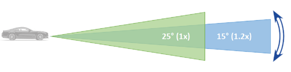
MEMS-type and prism-type LiDARs can dynamically change the vertical field of view. This can be used in two ways. The first method is to narrow the viewing angle and increase the laser output accordingly. Thereby, the detection distance can be extended. The second method is to increase the resolution by narrowing the viewing angle without changing the resolution. This makes it possible to detect small objects at a greater distance. Both meet needs such as wide viewing on general roads and narrow viewing on highways. In addition, since it is possible to move the narrowed field of view vertically, it is possible to turn the field of view downward at the top or bottom of a slope.
ROI
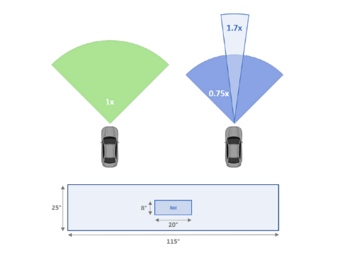
A Region of Interest (ROI) is defined as a region where the laser output is increased within a specified area of the field of view to extend the detection distance or improve object detection performance by increasing the resolution. The vertical field of view modification mentioned above is also a form of ROI in a broad sense, and the method is the same. The reason for specifically introducing it as an ROI is that, for example, in one manufacturer's LiDAR, by setting the laser output in the normal field of view to 75% and the laser output in the ROI area (a 20° x 8° region in the center of the field of view) to 170%, it is possible to obtain point cloud data even in the normal field of view while extending the detection distance in the ROI area. Furthermore, since this region can be set separately for each of the four MEMS, it is possible to change the region dynamically, for example, according to a curve. This is made possible by precise beam steering and laser output adjustment.
pixel addition
This is a method of grouping multiple pixels and treating them as if they were a single pixel, making it easier to capture weaker signals. A distant object or an object with a low reflectance has a low intensity of reflected waves and is buried in noise. However, by summing the reflected signals of multiple pixels, the S/N ratio can be increased. Therefore, it is possible to detect distant objects and objects with low reflectance. What's more, since this only adds calculations for the specified pixel group, the result of pixel addition can be output while the point cloud data of normal viewing angle and resolution remains unchanged. However, the point cloud data obtained by pixel addition has lower resolution and distance accuracy. Also, since the data bandwidth and processor load will increase, it is necessary to take this into consideration when designing.
Anti-interference
Close-wavelength lasers emitted from sunlight and other LiDARs cause noise. However, in recent years, each manufacturer has implemented interference countermeasures. There are various methods, such as limiting the angle of light entering the photodiode to the reflection direction so that only the reflected light of the laser emitted by itself is received, or patterning the laser light and receiving only the reflected light of that pattern. is also being done.
blockage
Blockage is a state in which foreign matter adheres to the LiDAR laser emission port and the windshield, which is the receiver of reflected light. In such a case, it is necessary to report the abnormality to the upper ECU because the part where the foreign matter is attached cannot be detected normally. If the system has a debris removal device such as wipers or high pressure air, activate it. If the autonomous driving level is 3 or lower, the driver can take over driving in the event of an abnormality, but if the level is 4 or higher, the system needs to continue driving, so a foreign matter removal device will be indispensable.
computer vision
As mentioned earlier, LiDAR is used in autonomous driving vehicles for object recognition and self-localization. While the point cloud information output by LiDAR already contains coordinate data for each individual point, for use in autonomous driving, perceptual processing is required to determine what the object is as a set of points. This article will explain the functionality using a representative example.
The typical functions of LiDAR-based perception software can be classified into three types: object recognition, drivable area determination, and ground landmark output.
object recognition
Object Recognition is actually a package for recognizing, identifying, tracking and predicting objects. The first is single detection that identifies the type of object in a single frame, and the movement detection that calculates the direction and speed of motion in multiple frames. Furthermore, the information from these two detectors is combined for tracking and prediction. Identifiers are identified as cars, large vehicles, motorcycles, bicycles, people, and so on. This information is linked with the unique ID of the object and sent to the upper ECU.
drivable area
At autonomous driving levels 4 and above, the system, rather than the driver, takes over the operation, requiring it to recognize drivable and parking areas. While processing varies depending on the software, some software classifies each point in the point cloud into two classes for each frame: potential for collision and non-collision. Point clouds classified as potential for collision are further divided into objects and obstacles. Point clouds classified as non-collision include flat ground, objects of a height that does not pose a problem when driven over, objects that do not pose a problem when driven underneath, and point cloud noise. This information, like object recognition, is also transmitted to the higher-level ECU. Furthermore, the implementation of functions to correct the vehicle's movement in combination with lane marking information such as white lines and sensors such as IMUs is also planned.
Landmark detection and tracking
As already mentioned, self-localization is essential for self-autonomous driving vehicles to accurately perceive where they are running on the map. Techniques such as NDT (Normal Distribution Transform) matching are used for matching with maps. This is to estimate the position of the vehicle by matching the characteristic landmarks on the map with the landmarks in the LiDAR information obtained while driving. Thus, it is this capability that detects and tracks distinctive landmarks such as vertical objects such as utility poles, horizontal objects such as guardrails, and large flat surfaces such as bridges and signs. These pieces of information are also sent to the upper ECU.
In this way, information such as objects existing in the operating area, travelable areas, and landmarks is provided to the host ECU. As a result, functions such as obstacle avoidance and route generation required for autonomous driving are realized.
Calibration
Considering application to mass-produced vehicles, a calibration function is also required. The first is pre-shipment calibration used at service centers such as factories and dealers. This is a function that detects a target placed at a specified position and automatically corrects the origin for the mounting position of the sensor. Also, while driving, the vehicle height and tilt change dynamically due to changes in loading conditions, suspension, and tire pressure. This is a function to dynamically correct these.
In sensor fusion, it is necessary to correct the difference between each other's coordinate system from the vehicle's coordinate system, and such real-time calibration will be essential for more accurate sensor fusion.
Challenges of LiDAR
Size/Mass/Cost
Although LiDAR has unrivaled performance, it still lags behind radar and cameras in size, weight, and cost. LiDAR has many components, so it can't be helped, but the increase in sales volume will lead to cost reductions to some extent. In the future, it is expected that small size, light weight, and low cost will progress through the evolution of parts such as laser arrays optimized for LiDAR and integration of light receiving units and signal processing units.
Reliability/Quality
Each company conducts reliability tests based on international standards and is proceeding with compliance, but the reliability evaluation specifications of Japanese car manufacturers are the culmination of know-how based on past experience, and they are more than international standards. are often subject to strict conditions and judgment criteria. In order to pass the test, there are many things that should be taken into consideration from the design stage, so I would like to briefly describe typical reliability specifications.
Considering installation outside the vehicle, the operating temperature range is -40°C to 85°C, and IP69K level is required for the protection level and waterproofness of the housing. In addition, each car manufacturer has its own high-pressure washing test specifications, so caution is required. As for the vibration test, rather than the vibration test at a fixed frequency, the random excitation test with the waveform specified by the car maker is more likely to cause problems. In addition, there is also a 100G class impact test, so caution is required. In terms of temperature and humidity, high temperature and high humidity and thermal shock are severe, but since the test conditions and judgment criteria are different, it is difficult to incorporate them into the design. EMI/EMC is relatively easy to consider since many of them conform to international standards rather than the physical tests mentioned above. Mutual understanding is essential for quality documents, as customs in Japan and overseas are slightly different.
In addition, there are many hurdles to adopting in mass-produced vehicles, such as functional safety and handling of environmentally hazardous substances.
Functional safety
Regarding functional safety, it is important to fully understand the standards, but it is necessary to set safety goals together with car manufacturers and system suppliers. Please use it as a reference when selecting parts and designing.
Summary
It is almost possible to replace a camera with LiDAR alone. However, this does not mean that LiDAR alone can be used for autonomous driving, but rather that the camera can be fully utilized as a redundant sensor. There is a high possibility that the same error will occur with the same type of sensor when the camera cannot detect it correctly. Therefore, detection omissions, false detections, and false recognitions can be prevented by detecting with different types of sensors such as LiDAR and radar. Combining multiple sensors like this is called sensor fusion, and this is exactly what autonomous driving vehicles need.
LiDAR has improved in performance and reliability in recent years, and has finally reached a level where it can be installed in vehicles. In addition, the need for LiDAR is very high in other mobility such as construction machinery, agricultural machinery, railroads, ships, and aviation, with keywords such as automation and safety. And LiDAR is beginning to be used in industries such as security and smart cities, such as intersections, railroad crossings, and platform doors. In this way, the market size of LiDAR is expected to reach several hundred billion yen in 2025, and its applications will continue to expand. Once they start being installed, they will become smaller, have higher performance, and cost less, just like mobile phone cameras.
In any case, I hope that new technologies like this can solve social issues.
Inquiry
the Company, Macnica, provides various products and services related to LiDAR. If you have any questions or requests regarding LiDAR, please feel free to contact us below.