- Smart City/Mobility HOME
- Search by use case
-
Search by product/service

- event·
seminar - Column
- Inquiry
Various sensors capable of distance measurement are appearing in the world. This time, we will introduce the basic technology and application examples of a stereo camera that can acquire 3D point cloud data such as 3D-Lidar at the same time as images.
By the way, why do readers search for stereo camera articles? Many people are looking for a better range sensor to realize the functions necessary for automation, improve efficiency, and improve safety in their own products, factories, and construction sites. As a result of reading articles with such expectations and considering them, there are many cases where although the technology is interesting, it cannot be put into practical use. Therefore, in this article, we will take up a practical stereo camera made by ITDLab and introduce the functions necessary for practical use.

What is a stereo camera?
A stereo camera is, as the name suggests, a sensor that can measure distance, that is, one of the distance sensors, which consists of two cameras.
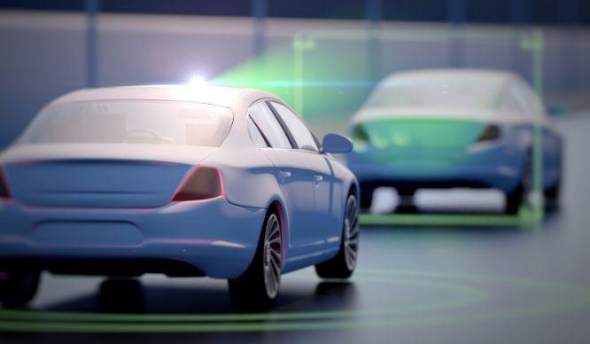
In the automotive field, it is already used in automobile driving support systems, so I think it is easy to imagine collision prevention assistance and obstacle detection for moving objects. Recently, due to the improvement of distance accuracy due to the development of sensors, it is also attracting attention for its use in various other fields such as picking robots. Both cases have been chosen as a replacement for the “human eye” in order to realize the excellent spatial comprehension ability that humans have, which allows them to make quick judgments, in their respective systems.
In the next section, I will explain why stereo cameras are able to reproduce the excellent spatial awareness that humans have acquired through certain training since they were babies, along with the principle of distance measurement.
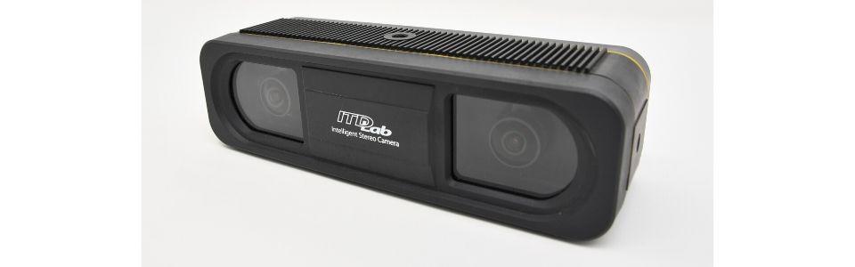
Stereo camera from ITDLab
Distance measurement principle of stereo camera
As shown in Fig. 1, the principle of distance measurement is explained using the case where there is a black point object in front of the camera as an example.
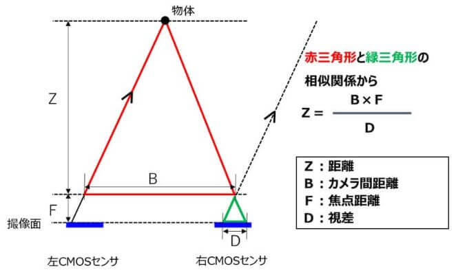
Figure 1: Image of stereo camera ranging principle
Connecting the object and the left and right CMOS sensors creates a red triangle whose base is the distance between the cameras. Considering the line of light incident at the same angle as the red triangle, and extrapolating the incident line to the left CMOS sensor to the right CMOS sensor part, a green triangle with the imaging surface as the bottom is completed. The bottom of this green triangle is called the difference in appearance from the left and right CMOS sensors, that is, "parallax." Here, the red triangle and the green triangle have a similarity relationship, so the distance Z from the stereo camera to the object can be obtained from the inter-camera distance B, the focal length F of the CMOS sensor, and the parallax D using the above formula. .
Since the inter-camera distance B and the focal length F have unique values for each camera, it can be said that the distance Z to a certain point can be obtained if the left-right deviation called parallax is known. Similarly, by calculating the distance to all feature points on the screen, the depth information in the screen and the vertical and horizontal pixel position information of the CMOS sensor (represented by 640 horizontal × 480 vertical pixels for VGA) can be used to create a 3D image. Positional information, so-called XYZ positional information, can be obtained, and it is possible to grasp the space close to humans.
Then, wouldn't it be possible for LiDAR and millimeter waves, which can similarly obtain XYZ information, to perceive space in the same way as humans? I wonder, but the answer is no. We can understand 3D positional information, but with LiDAR and millimeter waves, it is just a point cloud, which is different from how humans perceive space. When we imagine our familiar roads in our minds, we don't remember them in point clouds, do we? That's right, images are necessary for human-like spatial understanding. A stereo camera can acquire an image simultaneously with a point cloud with XYZ positional information. By obtaining information also known as RGB-D (RGB: image information + D: depth/distance information) at high speeds such as 60 fps, it is possible for the first time to achieve spatial recognition close to that of humans.
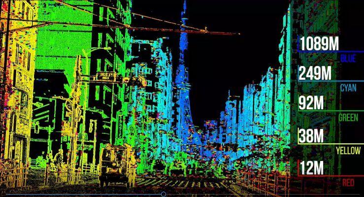
By the way, I have said that it has a spatial grasp close to that of humans, but how accurate is the human distance interval? Please imagine a scene where some tall building, such as Tokyo Tower or Sky Tree, is located about 500 meters away. Can you predict the distance that far? I couldn't. When I saw Tokyo Tower from a certain place during an experiment with a stereo camera, I thought it was at most 300m away, but I found out that it was nearly 1km away. I was stunned. On the other hand, the stereo camera clearly grasped that it was 1 km ahead.
Stereo image matching method
As described in the previous section, the stereo camera can determine the distance if the parallax D is known, but obtaining the parallax accurately greatly affects the performance of the stereo camera. There are many matching methods for finding parallax, but here we will introduce two typical ones.
・SGM (Semi Global Matching) method
A stereo camera has a weakness in that it cannot obtain parallax in areas where there is no image pattern. You can get a beautiful parallax image that can obtain data in the same way. On the other hand, since the correction configuration does not have to be correct, there is a tendency for erroneous parallax to diffuse and to obtain an unreliable distance distribution.
・SAD (Sum of Absolute Difference) method
In the SAD method, parts where parallax cannot be obtained are divided without data, and only highly reliable parallax is used. It is a method to find the optimal parallax D in a small area such as 4 × 4 pixels.
ITDLab provides stereo camera technology that uses the above SAD method and adds its own image processing technology. By devising the correction calibration and using a technology that suppresses the deviation of about 0.2 to 0.3 pixels to 0.1 pixels, the accuracy of the correction calibration is increased, the density of the correct parallax is increased, and as a result, sufficient density and accuracy high parallax image can be obtained.
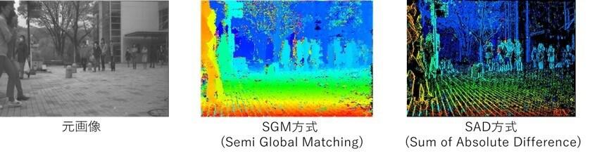
Figure 2: Differences in matching methods
You can see from the photo on the right in Fig. 2 that the parallax of the edges of people, trees, and tiles can be clearly obtained. The “edge” here refers to a place where there is a difference in brightness, that is, a place where there is a difference in brightness. You can get On the other hand, neither the SGM nor the SAD method can obtain parallax on a pure white wall where the surface is smooth and the luminance difference cannot be obtained. In that case, it is necessary to take measures such as pattern irradiation with infrared rays or visible light, but there are not many places full of white walls where even humans can not understand the distance interval, and in many scenes where people live It is in an environment where parallax can be obtained.
If you are interested in a stereo camera, where is it? I think there is an expectation that you want to grasp the accurate location information of. In that case, which is better, the SGM method or the SAD method? We think SAD is better when it comes to knowing the exact location.
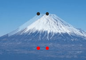
See Figure 3. A stereo camera will give you two photos that are slightly out of sync. Mt.Fuji is shown, and black dots and red dots indicate the places where Mt.Fuji on the left and right are the same. I think that anyone can judge that the black dot indicating the upper left part of the top of Mt.Fuji is the same place. On the other hand, the red dot on the middle of the stomach cannot be judged by the human eye as to whether or not it matches. Since the stereo camera calculates the parallax and distance from the amount of displacement on the image, the distance of the edge part can be obtained accurately, and the distance can be accurately obtained in places other than the edge where there is no brightness difference, such as the middle part of Mt.Fuji. It is characterized by being difficult. For these reasons, we are considering sensors for transport vehicles and picking robots as "obstacle sensors" that grasp the accurate position information of objects and avoid them safely and "robot eyes" for accurate picking. is progressing.
In addition, since highly accurate distance data (point cloud data) and images can be obtained at the same time and at the same coordinates, it is expected to be used as a replacement for LiDAR + monocular cameras.
Practical example of stereo camera
I tried to demonstrate how the real image from the stereo camera can actually be used.
In Fig. 4, the wrench was placed on a flat surface, but the parallax between the wrench and the flat surface is generated by the thickness of the wrench, making it possible to detect objects. At this time, even if the workbench is made of stainless steel with a similar color, it is possible to detect it without any problems because it is the parallax that is detected.
In the example of obstacle detection in Fig. 5, a small box (15cm x 20cm) is detected 3.5m away. Colored images are called "parallax images", which are color-coded distance data and displayed as a viewer. I wonder why it is possible to detect a box with similar colors around it in the image of the practical example.
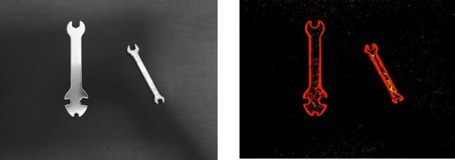
Figure 4: Original image of spanner and parallax image (dots with a certain distance are colored)
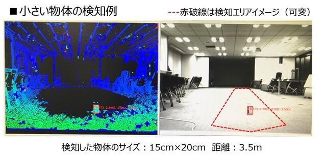
Figure 5: Obstacle detection example
If you zoom in on the area around the box as shown in Fig. 6, you can see that the color inside the red frame that indicates the box is slightly different than the surrounding area. Different colors indicate different distances, and distance images are displayed at each point in the red dashed line. Looking from the bottom of the dashed line, the distance starts at 3.00m, and the distance increases as you go up the image. It can be determined that there is a lump. The distance to the floor is also taken, but the distance increases as you go a little higher on the screen, so you can't see it as a block of the same distance. In this case (using a stereo camera with 300,000 pixels and a 90° angle of view), there are more than 100 dots of distance data of about 3.5m in the box, and it was easy to detect.
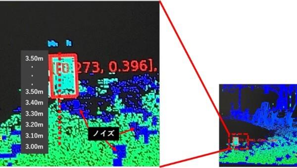
Figure 6: Enlarged image of Figure 5
Also, blue noise can be seen on the floor surface, but since the data of 5m or more is displayed in blue this time, it looks like a mass of the same distance. However, in actuality, adjacent dots such as 5m, 7m, and 10m are at different distances in the noise part, so there is no effect on detection. , making it easier to detect objects above the floor.
In addition to the 300,000 pixels used this time, ITDLab also has a lineup of high-resolution 1,000,000 pixel stereo cameras. By increasing the number of pixels of the camera and narrowing down the angle of view to 50° and 30°, it is possible to obtain more distance data for the same object, so it is possible to detect smaller objects and distant objects. increase. According to the user's target size and area, we offer object detection solution packages that deliver hardware and software ready to use.

Challenges and Autocalibration
So far, we have introduced the principles of stereo cameras and practical examples. Readers may have some problems that can be solved with a stereo camera, right? Here, I would like to tell you about the most important issues for the practical use of stereo cameras. As mentioned above, the stereo camera is a very good sensor, but it has been thought that it is difficult to put it into practical use. The reason for this was the difficulty of initial setup and the need for maintenance due to changes over time. A stereo camera captures images with two parallel cameras and calculates the distance from the amount of deviation between the two images, so the positional relationship between the two cameras is extremely important. At first glance, even if it is made according to the design, there are cases where it is necessary to prepare a special calibration board and make adjustments in order to know the correct positional relationship between cameras as an initial setting. Also, the positional relationship between the cameras will change over time, such as when the camera substrate is slightly deformed by the hot summer sun, so calibration (adjustment) work is required on the user side. . Even if a system using a stereo camera is developed and automation and efficiency are achieved, if the initial setting and maintenance of the stereo camera are required, facilities and equipment for that must be prepared, and it cannot be put into practical use. becomes difficult.
ITDLab's stereo cameras are equipped with a proprietary real-time automatic adjustment function (auto-calibration). As shown in the photo in Fig. 7, calibration is performed in everyday situations without requiring a specific pattern. If the positional relationship between the left and right cameras is misaligned, the parallax will not appear and the distance will not be correct as shown in Fig. 7 (2). When the state is detected, the automatic adjustment function (auto calibration) returns to the correct state in just 6 to 7 seconds. With this feature, we believe that ITDLab's stereo camera technology can be put to practical use in any environment and application.
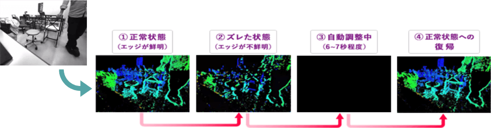
Figure 7: Images and transitions during auto-calibration
This time, we introduced the basic technology and application examples of stereo cameras, as well as the automatic adjustment function of ITDLab, which is essential for practical use. Please download the related materials below. Also, if you have any other questions or concerns, please contact us from the following.