- Semiconductor BusinessHOME
- Products and Services of Macnica,Inc.
-
technical information

-
Events and Seminars
- Handling Manufacturer
- Support
- Inquiry
- Click here to purchase products
- Semiconductor business e-mail magazine registration
![]()
![]() Narrow down by specifying conditions
Narrow down by specifying conditions
現在2172件がヒットしています。check
Concept of noise margin
ロジック回路の設計では、ノイズマージンの考え方が必要になります。分かったようで分かっていないのがノイズマージンだと思います。この考え方が誕生した時代と現在では環境が大きく変わっていますが、過去のノイズマージンの考え方を踏襲しているのが実情です。
What is noise margin
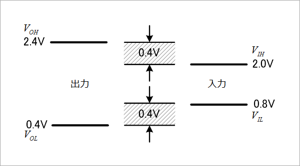
When connecting a logic IC, specify the output voltage of the front stage and the input voltage of the rear stage. As shown in Figure 1, the output voltage determines the maximum low and minimum high. For example, VOL ≤ 0.4V, VOH ≥ 2.4. The input voltage is VIL≤0.8V, VIH≥2.0V. Please refer to the column below.
What are VIH/VIL/VOH/VOL?
Therefore, it can be seen that even if the output has noise of 0.4V or less, it is okay. This 0.4V is the noise margin shaded in Figure 1.
Noise types include reflected noise, crosstalk noise, power supply noise, and ground noise. Simultaneous switching noise is considered a type of ground noise. In addition, external noise can also be considered. Reflection noise considers the bounce after the overshoot. Please refer to the column below.
How to decide the value of damping resistor?
Damping resistor value to be determined more easily
Crosstalk noise is noise received from adjacent lines. It can be calculated from the ratio of the characteristic impedance of the line and the output resistance of the driver.
Introduction to crosstalk
Near-end crosstalk and countermeasures
far end crosstalk
Crosstalk on cascaded lines
Power supply noise and ground noise are noises on the power supply and ground that appear superimposed on the output of logic circuits. Simultaneous switching noise is one type of ground noise, see the column below.
Simultaneous switching noise
If the total of these noises is suppressed to 0.4V or less, malfunction due to noise will not occur, but it will not be so easy.
Assuming a signal amplitude of 3.3V, 0.4V is 12%. For example, reflection noise is about 4% due to poor design. The crosstalk noise is about 5% when the crosstalk coefficient ξ is chosen to be 0.1. These two are 9%, so there is only 3% left. I'm pretty worried.
In the TTL era, the typical value of VOL was about 0.25V, but the typical value of VOH was 3V or more. Therefore, the actual noise margin was more generous on the High side. That is, it was not symmetrical between Low and High. Therefore, negative logic was used for asynchronous inputs such as reset (footnote 1) to avoid malfunctions due to asynchronous noise. Current CMOS circuits are completely symmetrical, so they can be either positive logic or negative logic.
Different people have different ideas about noise margin. There are cases where the worst design is used as shown above, but in most cases it seems that the settings are a little closer to the typical. The following is just an example, so please keep it as a reference.
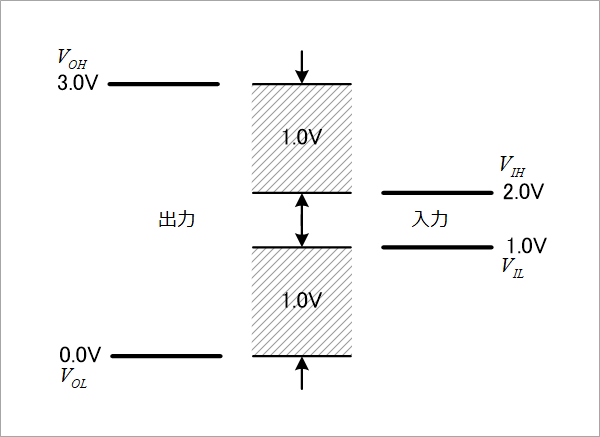
0.4Vmax of VOL is the standard of the TTL era, and is an impossible value for the current CMOS. For TTL, VOL was actually around 0.25V, but for CMOS it's 0V. There is an input current IOL specification, which is 0V unless a bipolar TTL is connected. VOH is also actually equal to the supply voltage, which we consider to be 3.0V (@Vcc=3.0V). VILmax is 0.8V in the standard, but it is actually 1V if Vcc=3.3V at about 30% of the power supply voltage Vcc. Figure 2 shows the voltage level and noise margin considering these factors. There is actually a noise margin of about 1V.
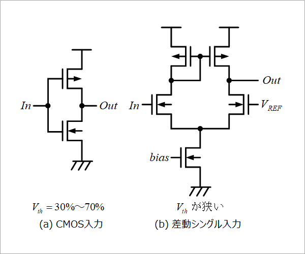
Furthermore, although the CMOS input circuit is a totem pole circuit as shown in Figure 3(a), it may use a differential single input as shown in Figure 3(b). In this case, if the input threshold voltage is chosen to be, say, 1.5V, the noise margin will be 1.5V.
The concept of noise margin that followed the TTL era is no longer suitable for current CMOS circuits. You might think that reflection and crosstalk shouldn't be so important, but that's not the case. I will talk about this next time.
(Footnote 1)
Ordinary signals are synchronized with the clock (synchronization signal), so even if noise is superimposed, malfunction will not occur if the timing does not match the clock timing. Signals that are not synchronized with the clock (asynchronous signals) cause malfunctions when noise is superimposed even if it is a single shot and exceeds the threshold level, so noise countermeasures are the most important signals.
What is Yuzo Usui's Specialist Column?
It is a series of columns that start from the basics, include themes that you can't hear anymore, themes for beginners, and also a slightly advanced level, all will be described in as easy-to-understand terms as possible.
Maybe there are other themes that interest you!