- Semiconductor BusinessHOME
- Products and Services of Macnica,Inc.
-
technical information

-
Events and Seminars
- Handling Manufacturer
- Support
- Inquiry
- Click here to purchase products
- Semiconductor business e-mail magazine registration
![]()
![]() Narrow down by specifying conditions
Narrow down by specifying conditions
現在2189件がヒットしています。check
Cascading Crosstalk
When considering crosstalk, the two lines usually do not change their characteristics on the way from the driver to the receiver. However, there are many cases where the characteristics change along the way.
for example,
・Purchase a unit from outside and connect it to your own designed board
・Partially narrow the wiring pitch only in places with high wiring density
・Cable connection exists in part of the wiring
・Only the characteristic impedance is considered, not the crosstalk coefficient
It's a case like
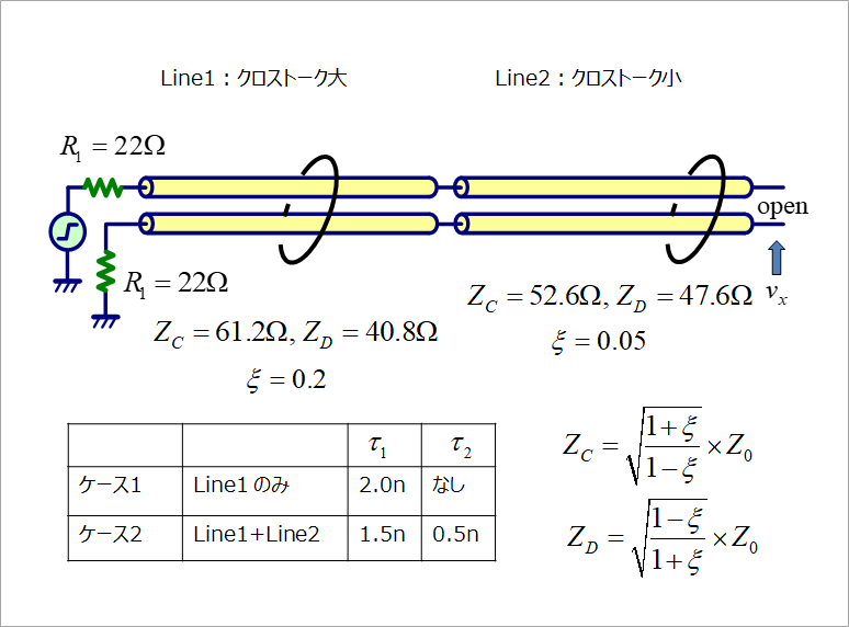
Figure 1 shows an example of cascading two lines. Line1 is a high crosstalk line with a crosstalk coefficient (footnote 1) ξ=0.2 and Line2 is a low crosstalk line with ξ=0.05. Two lines correspond to two modes, common mode and differential mode, and consider two characteristic impedances, ZC and ZD. (Footnote 2)
The relationship between the crosstalk coefficient ξ and the characteristic impedances ZC and ZD of the two lines is shown in the same figure. The characteristic impedance Z0 of both lines is 50Ω. (ξ: Greek lowercase letter Qsai)
Here, we consider two cases as shown in the table in the same figure.
・Case 1: Line1 only, delay time is 2ns (approximately 30cm)
・Case 2: When Line1 and Line2 are cascaded as shown in the figure
Both have the same overall wiring length (delay time) of 2ns. In case 2, 1/4 of the wiring length is a line with a small crosstalk coefficient, so it seems that crosstalk is smaller than in case 1.
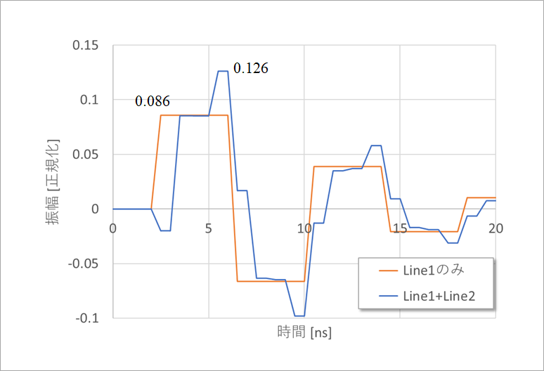
However, as shown in Fig. 2, looking at the results of analyzing the crosstalk in these two cases, the crosstalk in case 2 is 1.5 times greater than in case 1, even though lines with a small ξ are cascaded. increasing in extent.
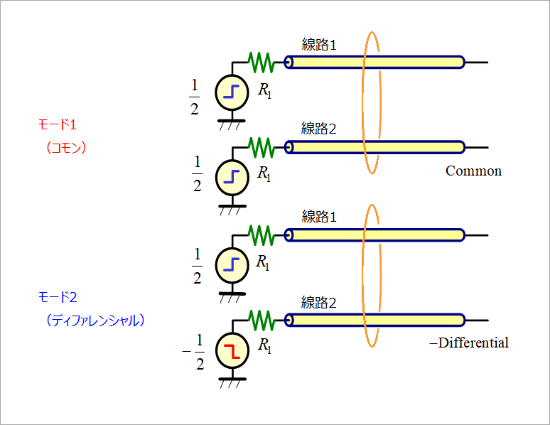
In order to investigate this cause, crosstalk calculation is performed by superimposition of Fig. 3. For this method, see Backward Crosstalk Factor Kb and Forward Crosstalk Factor Kf.
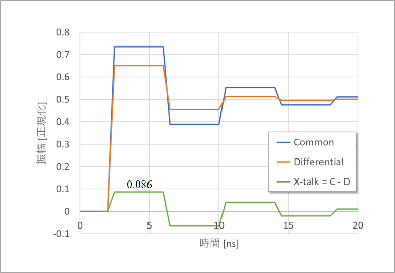
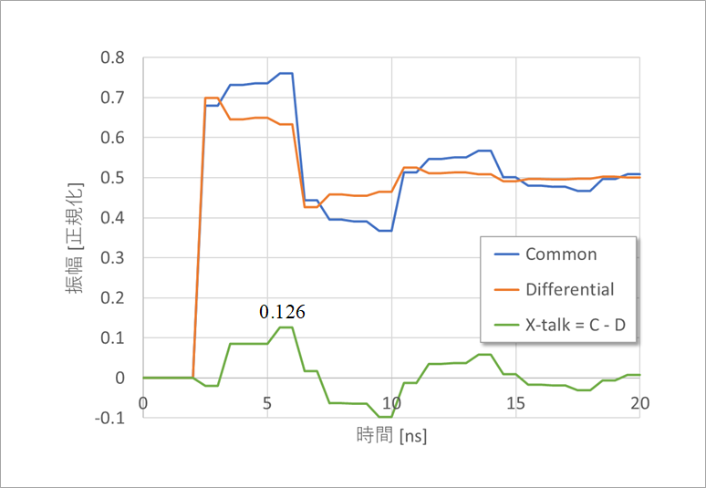
Fig. 4 shows the common and differential waveforms of only Line 1 in Case 1, and the difference between the two (the sum in Fig. 3) is the crosstalk. Figure 5 shows Case 2, when Line 1 and Line 2 are cascaded. A reflection occurs at the connection point of Line1 and Line2. As a result, taking the difference between Common and Differential increases crosstalk.
In the above example, Line1 is a line with large crosstalk and Line2 is a line with small crosstalk. Figure 6 shows an example of this reverse connection, that is, a cascade connection of Line2 and Line1. The timing of the crosstalk peaks is different, but the amplitude is approximately the same as in the previous example.
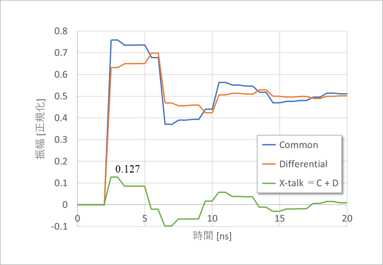
In the above example, Line1 is a line with large crosstalk and Line2 is a line with small crosstalk. Figure 6 shows an example of this reverse connection, that is, a cascade connection of Line2 and Line1. The timing of the crosstalk peaks is different, but the amplitude is approximately the same as in the previous example.
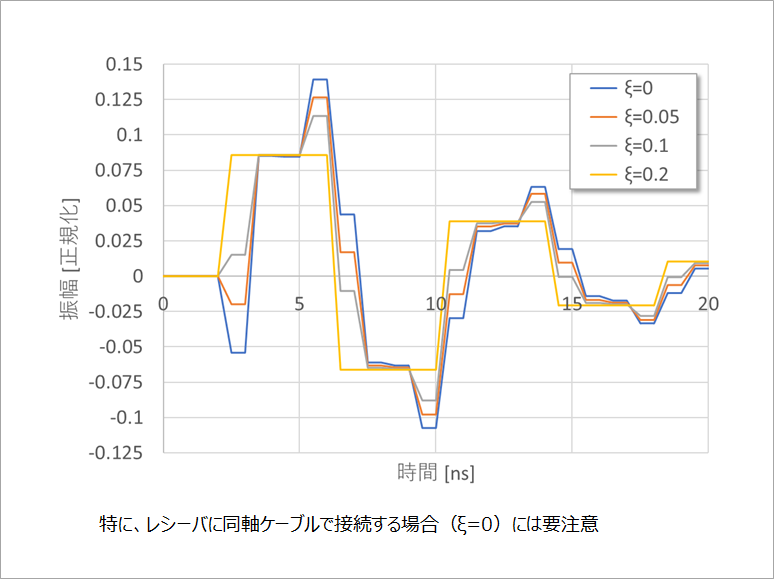
Figure 7 shows an analysis of the crosstalk when the Line2 crosstalk coefficient is changed. It can be seen that the smaller the crosstalk coefficient ξ of Line2, the greater the crosstalk. That is, crosstalk increases as the crosstalk coefficients of Line1 and Line2 differ. In particular, if Line2 is a coaxial cable (ξ=0), you will not be aware of this, so be careful.
(Footnote 1)
See footnote 2 in "Near-end crosstalk and countermeasures".
(Footnote 2)
Refer to characteristic impedance of two lines in "What is differential impedance?"
What is Yuzo Usui's Specialist Column?
It is a series of columns that start from the basics, include themes that you can't hear anymore, themes for beginners, and also a slightly advanced level, all will be described in as easy-to-understand terms as possible.
Maybe there are other themes that interest you!