- Semiconductor BusinessHOME
- Products and Services of Macnica,Inc.
-
technical information

-
Events and Seminars
- Handling Manufacturer
- Support
- Inquiry
- Click here to purchase products
- Semiconductor business e-mail magazine registration
![]()
![]() Narrow down by specifying conditions
Narrow down by specifying conditions
現在2182件がヒットしています。check

Logic circuits basically switch between two (rarely multi-valued) levels to represent a state. In the case of a typical CMOS (Complementary Metal Oxide Semiconductor), the levels of supply and ground voltage (0 volts) are assigned to logic "1" and "0".
The supply voltage used to be 5 V standard. Starting with DTL (Diode Transistor Logic) and TTL (Transistor Transistor Logic) in the 1960s, 5 V logic remains today. These bipolar devices could not swing all the way to the supply and ground voltages, and even at 5 V they had a logic swing of around 3 V. After that, CMOS became the center of logic, allowing full power supply swing. A term that is not often used in the logic field, but in the analog field, obtaining the full swing of the supply voltage is called Rail-to-Rail.
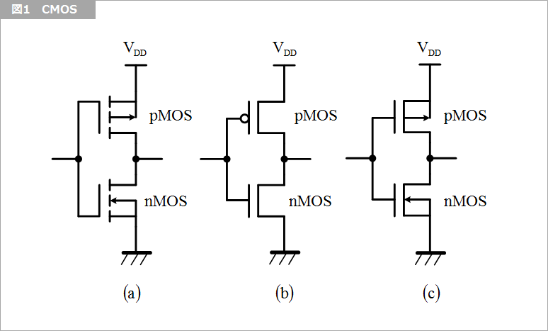
A current change occurs when switching between two logic levels. One is the so-called shoot-through current in CMOS. As shown in Figure 1, CMOS has a circuit configuration called a totem pole in which pMOS (p-channel MOS) and nMOS (n-channel MOS) are stacked vertically.
As an aside, either (a), (b) or (c) in the same figure is often used for drawing CMOS circuit diagrams. (a) is a JIS defined style, strictly speaking, an enhancement type (footnote 1) MOS circuit diagram. Enhancement type MOS is used for CMOS. I remember that (b) was the writing style specified by MIL. (c) seems to be a simplified form of (a) and is often used in handwriting. (Footnote 2)
In CMOS gates, the pMOS and nMOS are complementary to each other: when the pMOS is conducting, the nMOS is non-conducting, and vice versa. This is also the reason for the name CMOS. The input threshold voltage of this circuit is determined by balancing the pMOS and nMOS threshold voltages.
Near the input threshold voltage, there is a state where the pMOS and nMOS are half conducting rather than fully conducting or non-conducting, or momentarily both conducting. In this state, a large current flows from the power supply through pMOS and nMOS to ground. This current is called through current. In addition, current flows when charging and discharging the capacitance (capacitor) connected to the output.
In the case of elements connected to the output of an LSI, there is also a current that flows from the output to the wiring. At the moment the output changes, the output wiring is equivalent to connecting a pure resistance with characteristic impedance. “What is Characteristic Impedance?] See also.
If the number of gates whose logic changes is small, this current change does not have much significance, but if the number of gates whose logic changes at the same time increases, the peaks of the currents overlap, resulting in a large current change. . Due to this current change, the ground level changes due to the resistance and inductance existing on the ground plane inside the LSI. The current that flows to the ground includes not only the internal current, but also the return current of the current that flows when driving the wiring. A change in the ground level means that the internal gate, which is based on this ground level, behaves equivalently to a change in the input level.
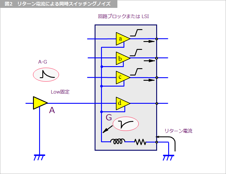
Figure 2 shows the principle of simultaneous switching noise due to return current.
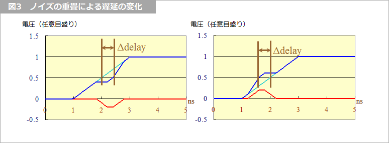
Let the part surrounded by a square be the circuit block or LSI. When the current flows out from the three output gates (a to c) in the same figure, the current driving the line is several tens of mA per output. If there is one return for three outputs, the return current will be three times the current per output. Since this current returns to the inside via the resistor and inductor, the internal ground voltage drops instantaneously as shown in the figure. Since the reference voltage (ground) of gate d in the figure drops as shown in G in the figure, the input voltage of gate d, which received low level logic outside this circuit block or LSI, is equivalently It becomes AG. The amplitude of AG rarely becomes large enough to cause malfunction, but if this noise overlaps with the rise or fall of the input signal to gate d, the delay time will change. Even if it becomes faster or slower, it may not be possible to secure the setup time and hold time, leading to malfunction.
Simultaneous switching noise can be dealt with by limiting the number of signals that operate simultaneously or intentionally shifting the timing. It is also important to ensure sufficient number of returns for the signal. If possible, it is also very effective to slow down the rise (fall) time of the signal. (Footnote 3)
Footnote 1
An enhancement-type MOS is one in which no drain current flows when the gate voltage (called VGS because it is the voltage relative to the source) is zero. In contrast, the depletion type is one in which the drain current flows even when the gate voltage is zero. In other words, in the depletion type, the gate voltage must be reversed (negative for nMOS, positive for pMOS) in order to make the drain current zero.
Footnote 2
In (a) and (c) of Figure 1, the arrows connect the substrate and the source, but in logic circuits this connection is not necessarily conscious, so it is often omitted. increase.
Footnote 3
In Altera devices, it is possible to adjust the rise (fall) time of output pins and bidirectional pins by setting the Quartus II development software. Set with ”Slow Slew Rate” or ”Slew Rate”.
For details, please refer to "Slow Slew Rate" and "Slew Rate" in "Quartus Getting Started Guide - How to Set Commonly Used Pin Options".
What is characteristic impedance?
Signal Quality Basic Knowledge Related Articles/Documents
What is Yuzo Usui's Specialist Column?
It is a series of columns that start from the basics, include themes that you can't hear anymore, themes for beginners, and also a slightly advanced level, all will be described in as easy-to-understand terms as possible.
Maybe there are other themes that interest you!