- Semiconductor BusinessHOME
- Products and Services of Macnica,Inc.
-
technical information

-
Events and Seminars
- Handling Manufacturer
- Support
- Inquiry
- Click here to purchase products
- Semiconductor business e-mail magazine registration


 Narrow down by specifying conditions
現在2240件がヒットしています。check

"What is power supply accuracy? (Part 1) As an example, we checked whether the output accuracy of the EN5311 is within the Cyclone® V FPGA's core power supply of 1.1V±30mV. It turned out that the EN53 series could be used with a power line of ±5%, although it was useless as a result.
This time, we will introduce the Enpirion® lineup for ±30mV accuracy, which was not possible with the EN53 series, and confirm whether they actually meet the accuracy requirements for core and transceiver power supplies.
what should i use?
The Enpirion® EN63 series can achieve an accuracy of ±30mV. The EN63 series is available in EN6310 1A, EN6337 3A, EN6362 6A, EN6360 8A, and EN63A0 12A versions. These devices have already proven their performance with Cyclone® V FPGAs, Arria® V FPGAs, and Arria® 10 FPGAs.
This time, we will take a detailed look using EN6337 as an example.
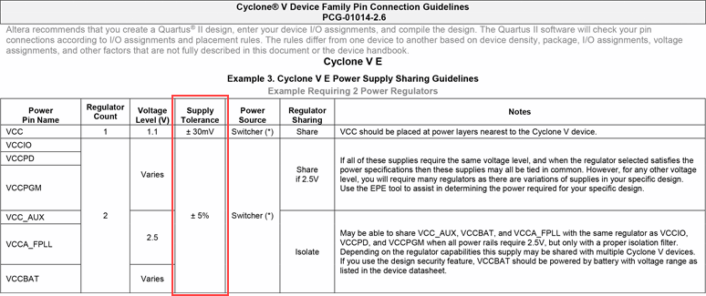
The image above is an excerpt from the Cyclone® V FPGA pin connection guidelines. The required voltage for each power line is listed in the Voltage Level (V) column. Furthermore, the required accuracy is written in the Supply Tolerance column. First, the required accuracy for the Cyclone® V FPGA's VCC (core power supply) is 1.1V ± 30mV, so I will add the following points step by step. First, it's 1.1V with an accuracy of ±30mV.
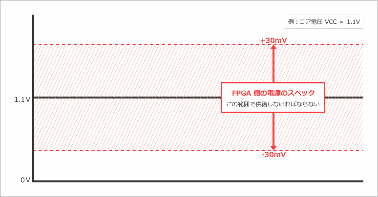
Now that we know the required precision of the FPGA, we next check whether the output of the power supply IC is within this specified value.
How do you check the accuracy of a power supply IC?
I checked the EN6337 datasheet and found the following table:
NOTE: VIN=6.6V, Minimum and Maximum values are over operating ambient temperature range unless otherwise noted. Typical values are at TA = 25°C.
| PARAMETER | SYMBOL | TEST CONDITIONS | MIN | TYP | MAX | UNITS |
| Feedback Pin Voltage | Vfb | Vin = 5V, ILOAD = 0, Ta = 25°C | 0.7425 | 0.75 | 0.7575 | V |
| VFB Pin Voltage (Load and Temperature) |
Vfb | 0A ≤ load ≤ 3A Starting Date Code: X501 or higher |
0.739 | 0.75 | 0.761 | V |
| Feedback Pin Voltage (Line, Load, Temperature) |
Vfb | 2.5V ≤ Vin ≤ 6.6V 0A ≤ load ≤ 3A |
0.735 | 0.75 | 0.765 | V |
EN6337 supports only Vfb mode and describes device accuracy for each Test Condition. The differences are as follows.
For ±1.0% accuracy: Vin = 5V/ Ta = 25° / Iload = 0A
±1.5%accuracy: Vin = 6.6V/-40° < Ta < 80°/0A < Iload < 3A / date code X501 or later
For ±2.0% accuracy: 2.5V < Vin < 6.6 /-40° < Ta < 80° / 0A < Iload < 3A
Ta is the ambient temperature of the device and Iload is the output current. As you can see, the test conditions are quite restrictive for ±1% accuracy. Considering the operation of the actual machine, it is more realistic to consider the case where the test conditions are -40°C < Ta < 80°C / 0A < Iload < 3A. There are conditions for ±1.5% accuracy, but the temperature range/output current range is also realistic. There are input voltage and date code restrictions, but if these are tight, consider ±2% accuracy. Please consider the accuracy after paying attention to the above.
There are other factors that must be considered, but the image below shows the image when considering the most convenient ±2% accuracy.
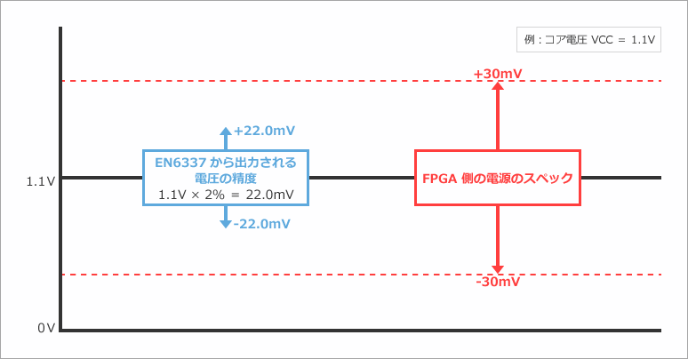
As will be explained later, when a DC-DC converter sets the output voltage, it is determined by the value of the resistor Ra/Rb placed in the feedback loop. The derivation is as follows:
[Formula 1] Vout = 0.75 * ( 1 + Ra/Rb)
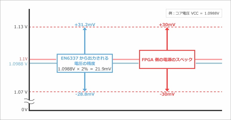
Since Ra is fixed at 200kΩ, in order to produce 1.1V, Rb must be set to 428.5714kΩ. A resistor of this value does not actually exist, so let's simply change it to 430kΩ. Then Vout will be 1.0988V.
Furthermore, the ±30mV required for the power supply has also changed. For the FPGA, it is acceptable as long as the input voltage stays between min 1.07V and max 1.13V. Therefore, if the output voltage of the DC-DC converter becomes 1.0988V, the min/max margins will also fluctuate accordingly (+ side: 31.2mV / - side: 28.8mV). The image is shown in the diagram below.
Does feedback resistance also affect accuracy?
Of course, the accuracy of the feedback resistors also matters. As an image, the part surrounded by the red frame in the figure below is Ra / Rb. This time, Ra = 200kΩ / Rb = 430kΩ.
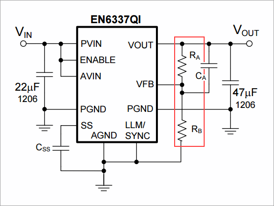
Explains why the accuracy of Ra / Rb should also be considered. If you check the datasheet, Vout is defined as follows.
[Formula 1] Vout = 0.75 * ( 1 + Ra/Rb)
What would happen to the above formula if Ra and Rb were each ±0.1% accurate? Since we consider +0.1% and -0.1% respectively, we need two equations Vout Max / Vout Min.
[Formula 2]Vout MAX = 0.75 * { 1 + (Ra*1.001)/(Rb*0.999) }
[Formula 3]Vout MIN = 0.75 * { 1 + (Ra*0.999)/(Rb*1.001) }
It turns out that the accuracy of Ra / Rb is more than enough for Vout. By the way, 0.75 in the formula refers to Vfb. As shown in the table above, Vfb has an accuracy of ±2%, so the total accuracy can be calculated using the following formula.
[Formula 4]Vout MAX = 0.75 * 1.02*{ 1 + (Ra*1.001)/(Rb*0.999) }
[Formula 5]Vout MIN = 0.75 * 0.98*{ 1 + (Ra*0.999)/(Rb*1.001) }
From the above, we understand that feedback resistance and Vfb should be considered as accuracy in Vfb mode. The images are summarized below.
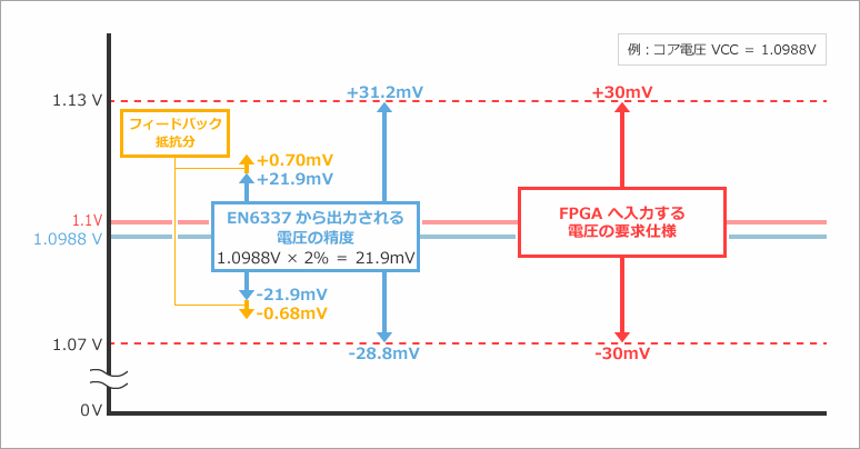
In addition, I will add how to find the voltage for the feedback resistance. As for the method of determination, from [Equation 4] and [Equation 5], which consider the accuracy of Vfb and the accuracy of the resistance, [Equation 6] and [Equation 7 ] can be calculated.
[Formula 6] Vout MAX = 0.75 * 1.02*( 1 +Ra/Rb )
[Equation 7] Vout MIN = 0.75 * 0.98*( 1 +Ra/Rb )
The voltage for the feedback resistance on the Vout_MAX side can be obtained from [Formula 4] – [Formula 6], and the voltage for the feedback resistance on the Vout_MIN side can be obtained from [Formula 7] – [Formula 5].
what else should i consider?
You also have to think about ripple. Please refer to the data sheet for this.
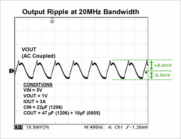
Considering the ripple, the final image is as follows.
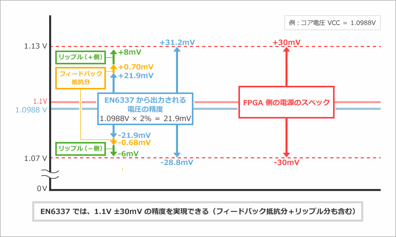
EN6337 was found to meet the ±30mV accuracy required by FPGAs. Isn't it pretty close? I think it's a lot of people who thought about it. Actually, the ripple is reduced by placing a capacitor close to the power supply pin. Therefore, there is some margin for accuracy. In fact, our EN63 series has a proven track record as a power supply for Cyclone® V FPGA / Arria® V FPGA / Arria® 10 FPGA, etc., so you can use it with confidence.
How was it?
I found that the power supply accuracy required for FPGA can be confirmed from the pin connection guidelines, and I found that EN53** / EN63** are supported by accuracy. Also, I think I've found the reason for this.
By referring to the above, when designing the power supply for the FPGA, confirm that the power supply accuracy satisfies the FPGA's required accuracy before selecting a device.
Click here for recommended articles/materials
Analog Circuits for Absolute Beginners: Enpirion® Series, Part 1 - What are the essential power supply elements for FPGAs?
Analog Circuits for Absolute Beginners: Enpirion® Series, Part 2 - What is the Power Consumption of an FPGA?
Analog Circuits for Absolute Beginners: Enpirion® Series, Part 3: What is Power Supply Accuracy? (Part 1)
FPGA power consumption types and calculation methods
Altera® FPGA Development Flow / FPGA Top Page