- Semiconductor BusinessHOME
- Products and Services of Macnica,Inc.
-
technical information

-
Events and Seminars
- Handling Manufacturer
- Support
- Inquiry
- Click here to purchase products
- Semiconductor business e-mail magazine registration
![]()
![]() Narrow down by specifying conditions
Narrow down by specifying conditions
現在2004件がヒットしています。check


Click here for product descriptions, quotations, demos, evaluation requests, etc.

Click here to apply for a seminar on this product
It has a wealth of useful functions for verification, and we will introduce assertion-based verification, which is one of the verification functions.
Due to the increase in circuit size and design complexity, the focus of FPGA development activities has shifted from design to verification. Assertion-based verification is already a widely used verification method for ASICs, and is one of the verification methods recommended for FPGA development as well.
Conventional verification method
Verification type
● Simulation
● Actual device verification (actual device debugging)
After the logic is completed, a simulation is performed, and the operation of the actual machine is confirmed after placing and wiring inside the FPGA. Fixes and changes should ideally be completed in the early stages of design, and squashing logic bugs in simulation is very important.
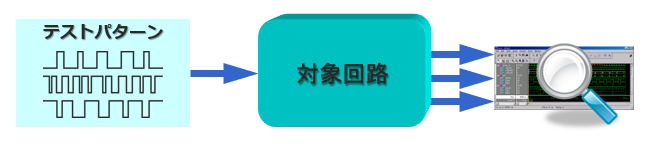
Features of simulation
Given an input vector, check if the output results are what you expect. The logic circuit to be verified is verified as a black Box, and if there is a problem with the output, it backtracks and narrows down the problem area.
Problems with traditional simulation methods
In recent years, as systems have become more sophisticated, designs tend to be more complicated. As circuit sizes grow, traditional simulation-based verification presents several challenges.
(1) High possibility of overlooking internal bugs!
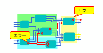
As the number of logic stages increases and the clock system becomes more complex, the signal path becomes more complicated. If the signal path becomes complicated, an erroneous signal generated inside the circuit may be masked by a subsequent block, preventing the erroneous signal from propagating to the output pin. It's hard to find bugs in logic simulation without false signals appearing on the output pins.
Since the waveform of the output pin is verified, not only a test bench that can generate internal bugs (test bench for each block verification) but also a test bench that propagates the signal to the output pin is required.
A product developed using such a verification method may encounter problems when various signal combinations are tested after it is released to the market, and bugs that were not found during verification are discovered.
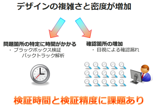
(2) Increase in debugging man-hours
Even if you are lucky enough to find a problem during pre-shipment verification of the actual device, the debugging work to search for bugs in a circuit with many logic stages, branches, and clocks is difficult. The reason is that the point (output pin) where the defect phenomenon was found and the defect location that caused it are different in time and place, and the flow of signals during logic design and the flow of signal analysis during debugging are in opposite directions. Because it becomes
In particular, if a bug is found during FPGA verification, it will lead to development delays because it requires a long compilation process for each correction. We recommend verifying the main functions with a simulator that is easy to fix, and verifying corner bugs and system verification with a real machine using a high-speed FPGA.
Assertion Based Verification (ABV)
Assertion-based verification (ABV) is a hot topic for RTL simulation challenges.
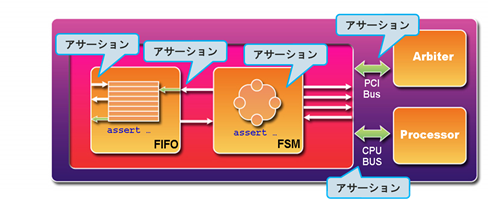
Assertion-based verification is verification that the behavior of internal signals is defined in advance in the circuit or interface section, and that the circuit is automatically monitored to ensure that it operates according to specifications. It is also known as white Box verification because it allows you to verify the behavior inside the circuit. Assertion constraints define areas where malfunctions are likely to occur, such as FIFO overflows and underflows, state machine interrupts and resets, arbitration fairness, and conditions such as comments in the RTL.
Have you ever experienced a case in the past when you frantically analyzed your own block that malfunctioned in an integration test, only to find that it was caused by a bug in the preceding block created by someone else? In order to avoid such unnecessary analysis work, it is convenient to automatically monitor the input signal by setting an assertion constraint on the input part of each block.
品質向上と検証工数削減に有効なアサーション・ベース検証の特徴をまとめます。
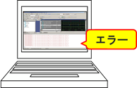
(1)自動検証で検証漏れを防ぐ
モニターピンによる内部検証と違って、アサーション・ベース検証は自動で監視します。
アサーションで期待動作を記述するため、期待動作と異なる結果が出た場合、シミュレーターがエラーとして表示します。ツールがエラーを出すたため、目視による検証漏れを防ぎ、検証工数を大幅に削減できます。
(2) Increase in debugging man-hours
Even if you are lucky enough to find a problem during pre-shipment verification of the actual device, the debugging work to search for bugs in a circuit with many logic stages, branches, and clocks is difficult. The reason for this is that the point (output pin) where the defect phenomenon was found and the defect location that caused it differ in time and place, and the flow of signals during logic design and the flow of signal analysis during debugging are in opposite directions. Because it becomes
In particular, if a bug is found during FPGA verification, it will lead to development delays because it will require a long compilation time for each fix. It is recommended to verify the main functions with an easy-to-fix simulator, and verify corner bugs and system verification with a real device using a high-speed FPGA.
(3) Clarification of verification items by defining the behavior of internal signals
If the verification items are not clear, it is difficult to know where to define the assertion constraints that act as signal behavior. The task of introducing assertion constraints seems cumbersome, but it is actually the most important task.
(4) Searching for bugs is fast because verification is performed near the defect location.
Most of the debugging effort is spent searching for bugs, not fixing them.
If you discover a problem in logic simulation or actual machine verification, you can quickly identify the cause of the problem by setting a trap with assertion constraints upstream of the problem signal. We will add to the internal design standards that an assertion function should be provided for the corresponding function. Repeating this work is very important to improve the design quality in the company.
When you introduce assertion-based verification, you design with verification in mind, which not only improves the quality of your in-house design, but also greatly reduces debugging man-hours.
<< Constraint syntax is very simple >>
To do assertion-based verification, it is necessary to define the internal behavior (functional specification). While assertion constraint definitions can be used in traditional Verilog or VHDL, specialized languages such as SystemVerilog (SVA) and PSL (Property Specification Language) simplify the description.
[Example 1]
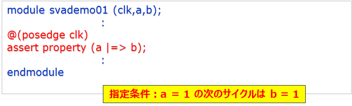
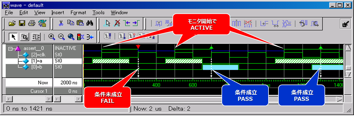
This example is a simple example of writing an assertion in a module called svademo01. This assertion says "b=1 is true in the next cycle after a=1 is true". Since there is @(posdge clk), the specification is to check the value of each signal at the rising edge of the clock. Looking at the waveform, you can see that the check starts at a=1, FAIL if b=1 does not occur in the next cycle, and PASS if true.
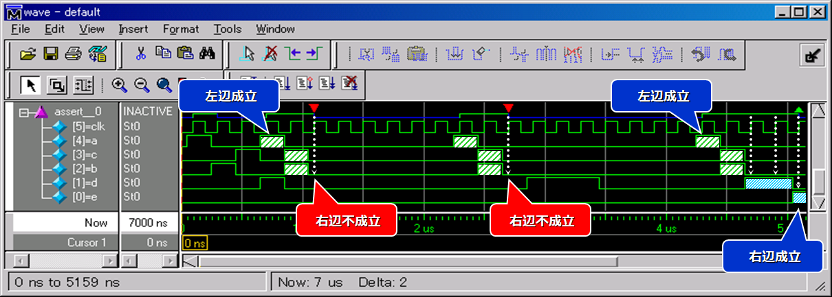
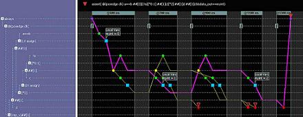
[Example 2]
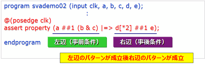
The following example is not a module called svademo02, but a program, and the assertion description is written in a separate file.
The contents of the assertion are: "After one cycle of a=1 on the left side, in the next cycle where the preconditions of b=1 and c=1 are satisfied, in the next cycle after repeating d=1 on the right side twice, e The post-condition of =1 is satisfied." This also has @(posdge clk), so it is designed to check the value of each signal at the rising edge of the clock.
Looking at the waveforms, the left and middle waveforms satisfy the preconditions, but fail because the postconditions are not satisfied. You can see that the waveform on the right is PASS because the precondition and postcondition are satisfied. In this way, you can also combine the states of several signals as preconditions and postconditions.
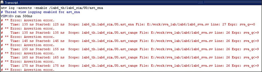
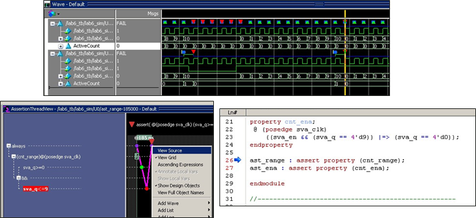
<< Analyzing Assertion Errors >>
Assertion verification using the GUI shows assertion errors in the Transcript window after running the simulation.
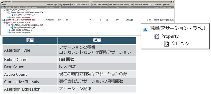
The Assertions window will reflect the results after the simulation.
The Wave window displays waveform results and indicates PASS/FAIL for assertions.
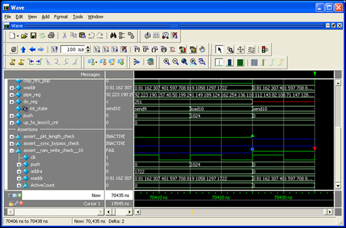
Questa/ModelSim has a useful feature for bug analysis, the Assertion Thread View (ATV). This ATV is the ability to split and debug simple constraints. You can easily see where the error is in the part defined in one line as shown in the figure below.
Debugging is also facilitated because the causes of assertion failures can be analyzed using the features provided by these GUIs.
Related Information
▶ Assertion-based verification
▶ code coverage
▶ Waveform comparison
▶ Extended data flow
Seminar/Workshop
▶ [Online Seminar] Assertion Validation with ModelSim <Free>
This seminar introduces the effects of assertion-based verification (ABV), code coverage, and extended data flow, which are debugging functions of Questa/ModelSim. In particular, assertion-based verification is the preferred verification technique, utilized in more than half of FPGA designs.
▶ Related events and seminars
Inquiry
Manufacturer information Top
If you would like to return to the manufacturer information top page, please click below.
Trademarks and registered trademarks owned by Siemens: here