- Semiconductor BusinessHOME
- Products and Services of Macnica,Inc.
-
technical information

-
Events and Seminars
- Handling Manufacturer
- Support
- Inquiry
- Click here to purchase products
- Semiconductor business e-mail magazine registration
![]()
![]() Narrow down by specifying conditions
Narrow down by specifying conditions
現在2168件がヒットしています。check


hello.
My name is Intel F. Hanako and I provide technical support for Intel® FPGA products at Macnica.
Quartus ® When using Prime Standard Edition or Lite Edition, FPGA functional simulation is Easy to do with NativeLink and recommended I informed you before.
In that case, some users may find it a little cumbersome to operate the iteration every time from the Quartus Prime menu.
In such a case,
How about running it from ModelSim (*) using only scripts for NativeLink simulation?
* Including ModelSim – Intel FPGA Edition, ModelSim – Intel FPGA Starter Edition
This time, I will introduce how to generate a script file for simulation and how to use it in ModelSim.
Hanako's recommended points♪
This method can automatically generate a script that summarizes all the user design files used in the design and the IP simulation library.
ModelSim does not start and run automatically like NativeLink does, only script files are generated.
This eliminates the need for users to manually cut and paste separate generated simulation scripts for each IP.
You can prevent missing sources and libraries that simulation tools should read.
Target environment
| Quartus Prime |
Quartus Prime Standard Edition Quartus Prime Lite Edition (* For Quartus Prime Pro Edition, see this content.) |
| Simulation tool (Note 1) |
ModelSim PE / ModelSim SE / Questa ModelSim - Intel FPGA Edition (includes Starter Edition) |
Note 1: For the supported version of each tool, please check the release notes of the version of Quartus Prime you are using.
Note 2: All schematic designs (.bdf) must be converted to HDL.
<Reference FAQ> Q: I want to simulate a design with a schematic in ModelSim, but it doesn't work.
Advance preparation
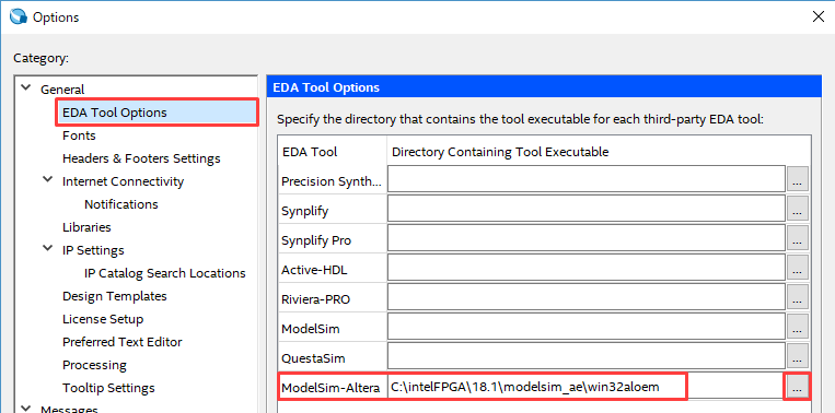
1) EDA tool environment settings
① Click EDA Tool Options under Tools menu ➤ Options ➤ General in Quartus Prime.
② Click the browser button on the right side of the line of the simulation tool name to be used, and select where the execution program of the simulation tool is saved.
Specify the absolute path of the folder.
For example, for ModelSim - Intel FPGA Edition (for Windows), specify the win32aloem folder where modelsim.exe is located.
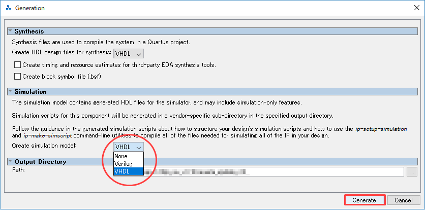
2) Generating a simulation model for the IP
If the module created by Platform Designer in the design or the IP called by IP Catalog is "activated based on Platform Designer", select the language from "Simulation model generation option" when generating. Then run Generate. (If not selected, the related files for simulation will not be generated and the simulation cannot be executed.)
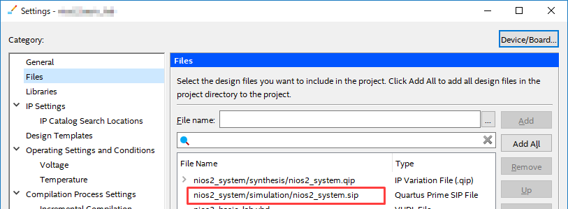
3) Register all design files in the project
Register all the designs (user designs, IP designs) required for compiling with Quartus Prime in the project using the menu below.
Project menu ➤ Add/Remove Files in Project
If your design contains other IP or modules created with Platform Designer, be sure to register the <ip_name>.sip file as well as the <ip_name>.qip in the generated folder.
<Related FAQ> What kind of file is a .sip file?
Where the .sip file is generated depends on whether you created the module in IP Catalog / Platform Designer.
Note that some IPs created with the IP Catalog do not generate their own simulation models or .sips (for example, ALTLVDS_RX/TX, ALTPLL, RAM: 2-PORT, etc.). In that case, register only the design files for logic synthesis in the project.
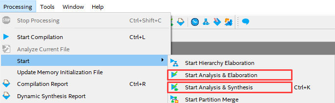
4) Execute Analysis & Elaboration
To generate the script file (because it is one step of NativeLink execution), you must run Analysis & Elaboration or Analysis & Synthesis.
As a result, the lineup and location (save path) of the set of design files including the IP modules required in the Quartus Prime project are taken up as information and reflected in the script file later.
Processing menu ➤ Start ➤ Start Analysis & Elaboration (or Start Analysis & Synthesis)
5) EDA tool settings and testbench registration
Configure EDA Tools Settings and NativeLink Settings.
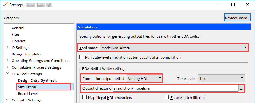
(1) Select Assignments ➤ Settings ➤ EDA Tool Settings ➤ Simulation, and select the name of the tool used for simulation in Tool name.
* For ModelSim - Intel FPGA Edition, select ModelSim-Altera.
(2) Set the following in the EDA Netlist Writer settings frame.
・ Format for output netlist : Verilog HDL (See Hanako's point♪)
・ Output directory : simulation/modelsim (default)

Hanako's point♪
Even if the simulation model and testbench when creating the IP are in VHDL, it is recommended to select Verilog HDL for this option.
This choice of language affects the vsim -L command in the NativeLink executable script.
In recent IP, even if VHDL is specified for the language selection of the simulation model, the lower model is often configured with SystemVeriog.
Inevitably you will need a simulation library for Verilog. In that case, use the vsim -L command to install all Verilog libraries.
Since it is necessary to specify it, please use Verilog HDL for Format for output netlist even if you generate a model in VHDL.
As for the simulation library for VHDL, since declarations are written directly in the source generated when creating the IP, you can use the vsim -L command to
Even if it is not specified, it will be handled.
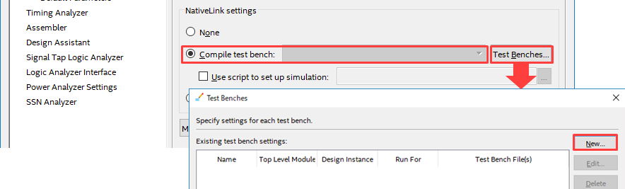
③ Register the testbench in the NativeLink settings frame.
Select Compile test bench and click the Test Benches button. Then click the New button in the Test Benches window.
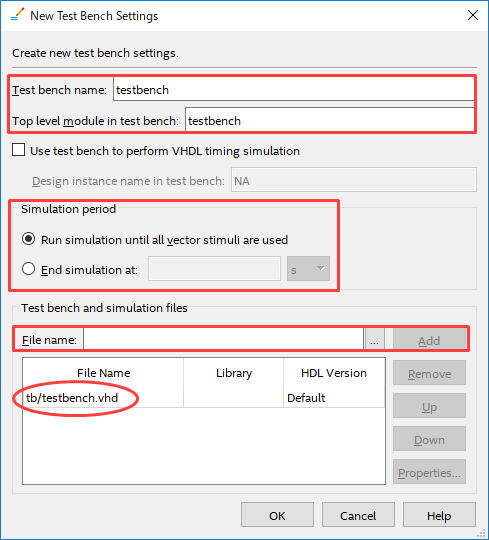
Set the following items in the New Test Benches Settings dialog Box.
・ Test bench name: Enter the module name of the test bench (enter the Top Level module in test bench column at the same time)
・ Simulation period : Set the end time of simulation execution
・ File name : Click the browse button and select the testbench file. Register with the Add button.
Close each window with OK to return to the Settings window.
(*Do not close the Setting screen and proceed to the next operation.)
Generate script file
Let Quartus Prime generate a simulation script file for ModelSim.
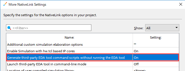
① Click the More NativeLink Settings button and enable the option to run NativeLink without tool launch (script generation only).
Generate third-party EDA tool command scripts without running the EDA tool = On
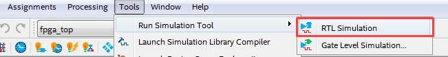
② Generate a script file.
Click Tools menu ➤ Run Simulation Tool ➤ RTL Simulation.
After execution, the following Information message is displayed in the System tab of the Messages window.
ID: 22036
For messages from NativeLink execution see the NativeLink log file <path to working folder>/<project name>_nativelink_simulation.rpt

Open the <project name>_nativelink_simulation.rpt file indicated in the message with a text editor and add
If you can see the message below, you're good to go!
Info: NativeLink simulation flow was successful
One of the following do files is generated according to the contents specified in EDA Tool Settings ➤ Simulation.
| Language specified in Format for output netlist | Script file generated in Output directory |
| Verilog HDL | <project_name>_run_msim_rtl_verilog.do |
| VHDL | <project_name>_run_msim_rtl_vhdl.do |
[Note]
Although the filename contains the language name, it is irrelevant to the content of the script.
ModelSim - IFEcommands are automatically applieddepending on the language format of theFPGA design file and testbench file.
For example,in a project with mixedVHDLandVerilog designs, compile the VHDLsource using the vcom command,
VerilogCompiling the sourcevlogThe script is automatically configured to run on command. (He's smart~♪)
The script file is now complete! !
Run script file in ModelSim
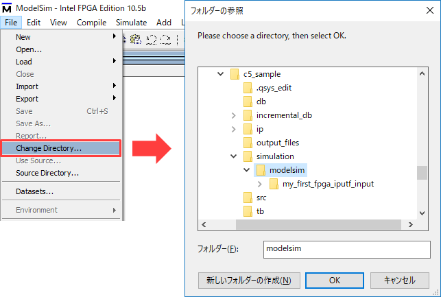
① Start ModelSim and select File menu ➤ Change Directory (or cd command).
Navigate to the folder where the script file was generated.
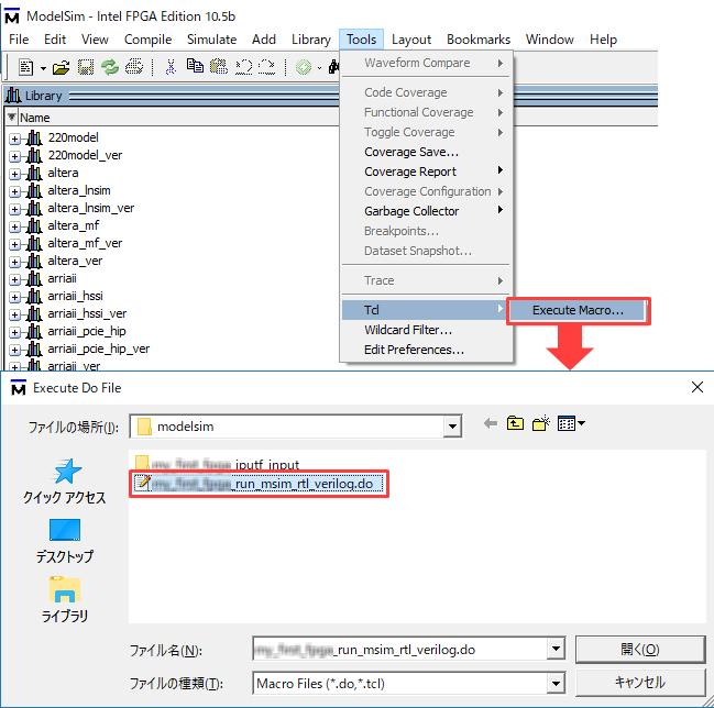
(2) Select and execute the script file from Tools menu ➤ Tcl > Execute Macro….
If you use the Transcript window to execute a command, it is a “do command”.
Example do <project_name>_run_msim_rtl_verilog.do
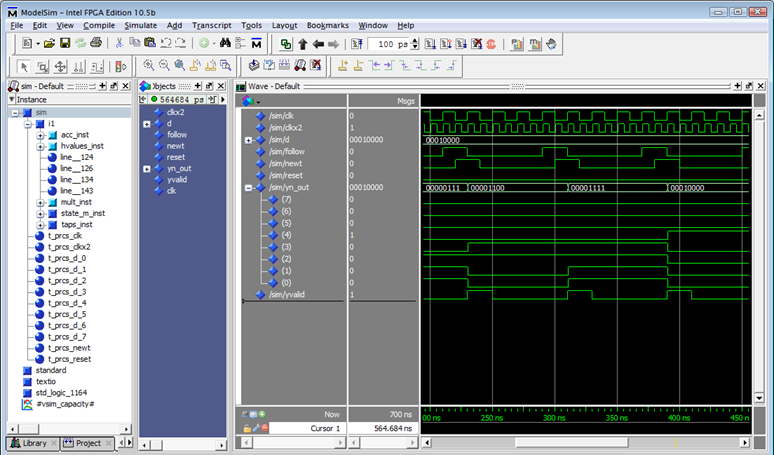
(3) The simulation is automatically executed.
By the command described in the script,
・Compile and execute sources, libraries, and simulation models (vcom/vlog commands)
・Load execution (vsim command)
・Add the signal to be observed to the Wave window (add command)
・Simulation execution (run command)
etc. will be executed.
④ Verify the waveform displayed in the Wave window.
Script file description
Quartus Prime generated by RTL Simulation (Tools menu ➤ Run Simulation Tool)
Here are some of the commands used in the <project_name>_run_ msim_rtl_verilog.do / <project_name>_run_ msim_rtl_vhdl.do files.
|
command |
Overview and example |
| vlib |
create a library 例: vlib rtl_work |
| vmap |
Mapping the logical library name to the path of the library on the filesystem 例: vmap work rtl_work |
| vlog |
Compile Verilog and SystemVerilog files into libraries Example: vlog -work work ./sample.v |
| vcom |
Compile VHDL files into libraries For example: vcom -work work ./sample.vhd |
| vsim |
load the design Example: vsim work.sample_tb |
| add wave |
Add Selected Signals to Wave Window Example: add wave * |
| view |
display the specified window Example: view structure |
| run |
run the simulation Example: run 500ms |
You can also add or edit commands in the generated script file and use it.
Add # at the beginning of the line to comment out.
For more information on commands and command options, see the ModelSim, Questa Command Reference Manuals.
Click here for recommended articles/materials
Let NativeLink solve your FPGA function simulation
How to Functionally Simulate a Design with Quartus ® Prime Pro Edition Generated IP in ModelSim