- Semiconductor BusinessHOME
- Products and Services of Macnica,Inc.
-
technical information

-
Events and Seminars
- Handling Manufacturer
- Support
- Inquiry
- Click here to purchase products
- Semiconductor business e-mail magazine registration
![]()
![]() Narrow down by specifying conditions
Narrow down by specifying conditions
現在2004件がヒットしています。check


hello.
My name is Intel F. Hanako and I provide technical support for Intel® FPGA products at Macnica.
The Quartus® Prime NativeLink simulation flow is the recommended flow for RTL-level functional simulation of designs containing IP for Intel FPGAs using an EDA simulator. Quartus Prime Pro Edition does not support NativeLink simulation. Is not ...
| Table 1. NativeLink Simulation Support in Quartus Prime | |
| Quartus Prime Pro Edition |
× |
| Quartus Prime Standard Edition |
〇 |
| Quartus Prime Lite Edition |
〇 |
If your design contains IP, it is not as easy as it requires setting up a simulation model (library) for the IP as well as a simulation model (library) for the Intel FPGA.
Therefore! here
Learn how to perform RTL-level functional simulation of designs containing IP for Quartus Prime Pro Edition users.
This time, we will introduce Questa* - Intel® FPGA Edition (hereafter referred to as Questa - IFE, including Starter Edition), Questa, and ModelSim as simulation tools.
For other EDA simulators, see the documents below.
Intel Quartus Prime Pro Edition User Guide: Third-party Simulation
|
Please also use this flow. For details, please see the following content. How to easily perform RTL simulation using the Run Simulation feature of Quartus® Prime Pro Edition |
Target software environment
| Corresponding Quartus Prime Edition | Quartus Prime Pro Edition |
|
covered in this content Simulation tool (Note 1) |
Questa - Intel FPGA Edition (including Starter Edition) (*2) or Questa, ModelSim |
*1: Please check the release notes of the Quartus Prime version you are using for the supported version of each EDA tool.
*2: Please use one that supports Pro Edition.
Generate Simulation Models for IP
In order to RTL-level simulate your IP, you must have generated a simulation model for your IP.
When creating an IP in IP Catalog or Platform Designer, in the Generation dialog Box that pops up when you run Generate HDL, specify the language in the “Create simulation model option” and select the corresponding tool to generate the script for running the simulation. To do.
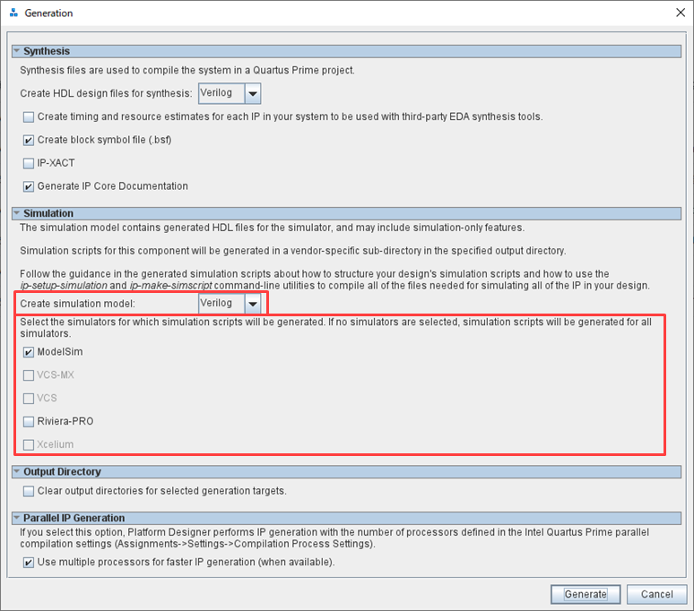
Then click the Generate (or Generate HDL) button to generate a functional model and script files for your simulation tool for that IP.
work flow
Below is a design containing IP generated by Quartus Prime Pro Edition.
Questa – A work flow for RTL level simulation with IFE (or Questa, ModelSim).
It is assumed that you have already created a Quartus Prime project and completed your design.
1. Register your design in a Quartus Prime project
2. Generate simulation scripts for IP
3. Create simulation script including user design
4. Simulation execution
1. Register your design in a Quartus Prime project
Register the design files required by Quartus Prime during compilation in the Quartus Prime project.
IP designs register *.ip files.
Project menu > Add/Remove Files in Project
2. Generate simulation scripts for IP
From the menu below, generate simulation scripts for all IP registered in the Quartus Prime project.
Tool menu > Generate Simulator Setup Script for IP
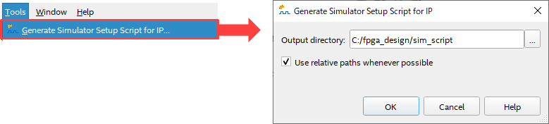
The currently open Quartus Prime project folder path is displayed by default.
For file management, we recommend that you prepare a separate folder for the script file and generate it there.
(The figure above specifies to create and generate the sim_script folder in the Quartus Prime project C:/fpga_design.)
3. Create simulation script including user design
① Open msim_setup.tcl in the mentor folder in the folder generated in step 2 with a text editor.
# # TOP-LEVEL TEMPLATE - BEGIN
from
# # TOP-LEVEL TEMPLATE – END
Copy all lines up to and paste into a new text file.
After that, save the file name as mentor.do (file name is arbitrary) in the same folder as msim_setup.tcl.
② Delete the first two characters (# and space) of each line.
(3) Edit the contents of the script according to the folder environment.
I will explain the commands from above.
set QSYS_SIMDIR <script generation output directory>
Specifies the folder path (absolute or relative) of Quartus Prime-generated scripts for IP simulation.
That is, the path specified in Generate Simulator Setup Script for IP.
In this example, it is the sim_script folder.
Example) set QSYS_SIMDIR ./

Hanako's point♪①
When setting with a relative path, the reference folder is the working folder of Questa - IFE, and by default the folder specified in Generate Simulator Setup Script for IP is assumed to be the working folder of Questa - IFE. If the working folder of Questa - IFE is set to another folder, set QSYS_SIMDIR to the path specified in Generate Simulator Setup Script for IP based on the working folder of Questa - IFE. Keep this in mind when specifying relative paths.
source $QSYS_SIMDIR/mentor/msim_setup.tcl
Load the IP simulation script.
No editing required.
set USER_DEFINED_COMPILE_OPTIONS <compilation options>
set USER_DEFINED_VHDL_COMPILE_OPTIONS <compilation options for VHDL>
set USER_DEFINED_VERILOG_COMPILE_OPTIONS <compilation options for Verilog>
Set the compilation options as required.
Type # at the beginning of the line to comment it out, as we won't be using it this time.
dev_com
Compile standard simulation models for Intel FPGAs.
No editing required.
This command will run on non-Intel editions of Questa and ModelSim.
Questa - IFE user is an unnecessary execution command, but it is automatically determined to be Quetsa - IFE and is not executed.
No need to comment out.
com
Compile the IP's simulation model.
No editing required.
vlog <compilation options> <design and testbench files>
Add command to compile all user design files and testbench files exceptIP designs.
The vlog command is a Verilog HDL source compilation command.
VHDL users edit to vcom.
ex) vcom <compilation options> <design and testbench files>
<compilation options> : Options can be set when compiling as needed.
For example:
You can specify the language version as well as the folder and library name in which to store the compiled results.
vcom -2008 -work work ../simple_counter.vhd
vlog -vlog01compat -work work ../simple_counter.v
For details on the options, see the Commands chapter in the Command Reference Manual for each simulator tool.
Check out our vlog or vcom.
<design and testbench files>: Specifies the path (absolute or relative) of the files to compile.
Hanako's Tweet ①
The Command Reference Manual is stored in the Questa - IFE installation folder.
Example) \\<tool_install_dir>\docs\pdfdocs\questa_sim_ref.pdf
set TOP_LEVEL_NAME <simulation top>
Sets the top-level testbench module/entity name.
This command is used by the elab / elab_debug commands to elaborate the top level.
Example) set TOP_LEVEL_NAME top_sim
set USER_DEFINED_ELAB_OPTIONS <elaboration options>
Set the elaboration options as desired.
Type # at the beginning of the line to comment it out, as we won't be using it this time.
elab_debug
The vsim command is run with -voptargs=+acc (options that enable visibility to objects in optimized designs).
If you don't want to optimize, use the command below.
elab
VHDL users can specify the Resolution by adding the -t option after the elab_debug or elab command.
Example) elab_debug -t 1ps
Resolution If nothing is specified, ns will be used.
Verilog HDL users rely on the Resolution stated in the testbench.
Hanako's point♪②
Add the add wave command before the run command to display the simulation results as a waveform.
To register all ports on the testbench, * (asterisk) OK!
Example) add wave *
run -a
Run the simulation.
-a is equivalent to -all. Run the time specified in the testbench.
If you want to specify a time, specify a space, time and unit after the run command.
Example) run 500ms
exit -code 0
This time it is not necessary because it is operated by GUI. Type # at the beginning of the line to comment it out.
Save the do file after editing.
4. Run the simulation
① Start Questa-IFE.
(2) Specify the work folder for simulation by File menu > Change Directory.
In this content it is C:/fpga_design/sim_script.
(3) Select Tools menu > Tcl > Execute Macro, and double-click the do file created in step 3.
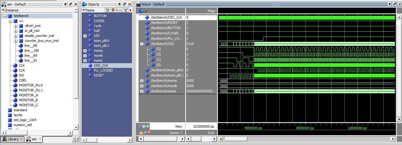
④ The contents of the script are executed, and the simulation results are displayed as waveforms in the Wave window.
Hanako's Tweet ②
If the design (including testbench or IP) is changed after the simulation is run, the source code should be recompiled and the simulation run again. In that case, enter # at the beginning of the command that does not need to be re-executed in the do file created in step 3 to comment it out and reuse it. (for example, dev_com)
This eliminates duplication of work and reduces man-hours.
With the above as a reference, let's easily perform function simulations with the Pro Edition!
Click here for recommended articles/materials
Altera FPGA Functional Simulation with NativeLink