- Semiconductor BusinessHOME
- Products and Services of Macnica,Inc.
-
technical information

-
Events and Seminars
- Handling Manufacturer
- Support
- Inquiry
- Click here to purchase products
- Semiconductor business e-mail magazine registration
![]()
![]() Narrow down by specifying conditions
Narrow down by specifying conditions
現在2168件がヒットしています。check

Power supplies and amplifier circuits are often composed of negative feedback amplifier circuits. Negative feedback refers to returning part of the output to the input in reverse phase. When the feedback fails, the response becomes unstable and, in the worst case, oscillates.
Considering the degree of stability of the negative feedback circuit is called stability determination.
The knowledge required for this
(1) Phase delay circuit and phase advance circuit
(2) Basic characteristics of operational amplifiers
(3) Relation between feedback circuit gain and phase
(4) Open-loop transfer function
(5) Stability judgment
(6) Phase compensation
is.
Each is described below in three parts.
lagging and leading circuits
A circuit consists of a combination of passive components such as resistors, capacitors and inductors and active components such as ICs and transistors.
Many of these are combinations of resistors and capacitors.
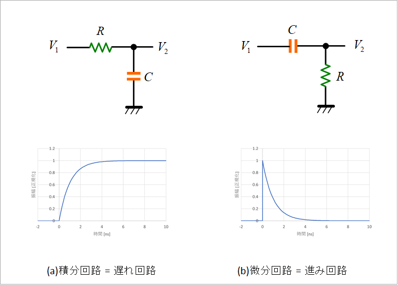
Figure 1 shows the simplest combined circuit of resistors and capacitors. (a) is called an integrator or delay circuit, and (b) is called a differentiator or lead circuit. These circuits consist of a set of resistors and capacitors, and are called first-order lag circuits or first-order lead circuits.
The names "integration" and "differentiation" come from the fact that when a square wave is applied to this circuit, the response is similar to that of integration or differentiation, as shown in the figure. Now consider the lagging and leading circuits.
Transfer functions of lagging and leading circuits
Figure 2 shows the respective transfer functions V2/V1 in equation form.
Both are called first-order because the degree of s in the denominator is first-order.
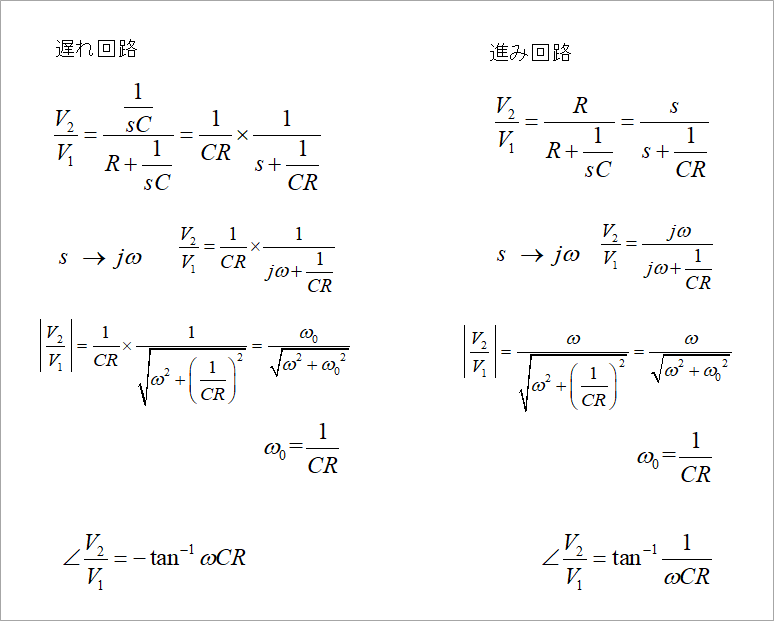
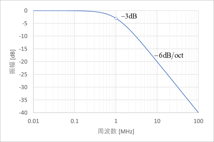
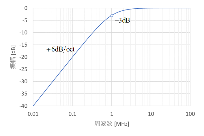
Figure 3(a) shows the absolute value of the first-order lag circuit in decibels (dB) when R = 400Ω and C = 400pF. The amplitude when the angular frequency ω0=1/CR is -3dB.
This first-order lag network rolls off linearly at frequencies above ω0. This slope is -6dB/oct or -20dB/dec. An oct refers to the musical octave, meaning that doubling the frequency results in -6dB (footnote 1), or halving. Dec means 1 decade, and means that if the frequency changes by 1 digit, the characteristic will change by 10 times (1/10).
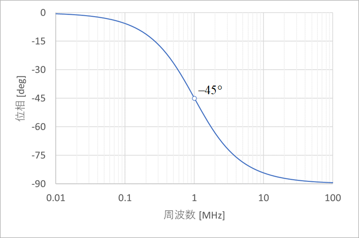
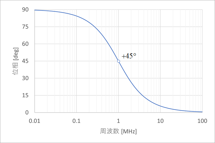
Figure 3(b) also shows the phase of the first-order lag circuit. It is -45° at ω=ω0.
Figures 4(a) and (b) are also the amplitude and phase of the first-order advance circuit.
Time response of lagging and leading circuits
Figure 5 shows the time response when a 1MHz (ω0) sine wave is applied to the first-order lag circuit. It is 0.125μs behind the input waveform. Since the period of 1MHz is 1µs, it will be delayed by 1/8, ie 360°/8=45°. See Figure 3(b). This delay varies with frequency.
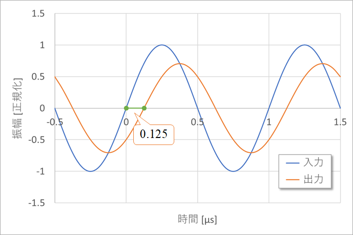
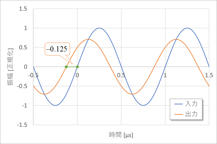
Figure 6 shows the waveform of a 1MHz sine wave added to the first-order lead circuit. In this case, it advances by 0.125 μs, so it advances by 45° as shown in Fig. 4(b).
The maximum delay of the first-order delay circuit is 90°, and if another delay circuit is added, it becomes a second-order delay circuit with a maximum delay of 180°. A delay of 180° will invert the waveform when considered as a sine wave. This is important in the feedback circuit, as will be discussed later.
negative feedback circuit
Figure 7 is a principle diagram of a negative feedback circuit.
This circuit consists of an amplifier circuit with a gain of A0 and a feedback circuit with β times the output (β<1). It is called a negative feedback circuit because the sign is changed for feedback.
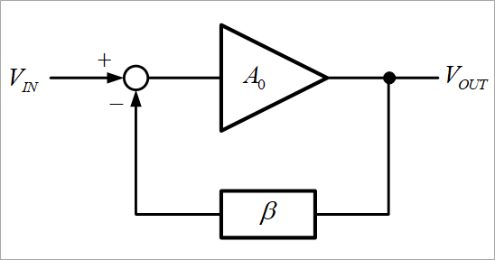
Assuming that the input voltage is VIN and the output voltage is VOUT, VIN and -β x VOUT are added to the input of the amplifier circuit, and the sum (the difference because the signs are different) multiplied by A0 is VOUT.
i.e.
A0×(VIN-β×VOUT)=VOUT
Solving for VOUT from this equation gives
VOUT=A0/(1+A0β)×VIN
becomes.
The gain G of this circuit is
G=VOUT/VIN=A0/(1+A0β)
, A0 is generally a very large value of 10 to the power of 5 or more, and β is a finite value, so 1 in the denominator of the above equation can be ignored,
G≒1/β
becomes.
β can easily be realized by dividing the resistance. See the actual circuit (Figure 8) below.
Amplifier circuit A0 often uses an operational amplifier.
A simple feedback circuit is a combination of resistors, and a complicated one is a combination of resistors and capacitors.
A very simple circuit, that is, a combination of an operational amplifier and a resistor to form an amplifier circuit that is several times larger, can form a stable circuit. need to do it.
Advantages of Negative Feedback Circuits
The advantage of the negative feedback circuit is
(1) Wide frequency band can be obtained
(2) Gain can be set stably
(3) Distortion and noise can be suppressed
(4) Lower the output impedance
Etc.
Negative feedback makes the gain smaller than it was before the feedback was applied, but it is widely used because the above advantages are overwhelmingly favorable.
As opposed to negative feedback, there is also positive feedback. Since it digresses from the main article, I write it as "digression 1" at the end of the article.
actual circuit
Figure 8 shows a negative feedback circuit using an actual operational amplifier.
The output resistance R0 of the operational amplifier is on the order of several tens of ohms, and since R0<<R1, R2, G=1/β=1+R1/R2. Get bigger.
If R1=0, then G=1 and the input and output voltages are equal. This circuit configuration is called a voltage follower circuit.
A voltage follower is used as a buffer circuit.
If R1=R2, then G=2.
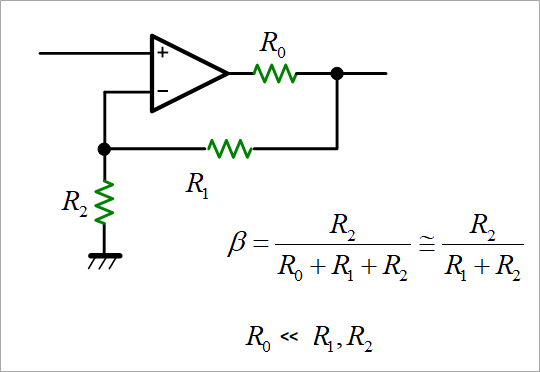
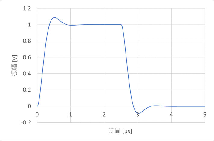
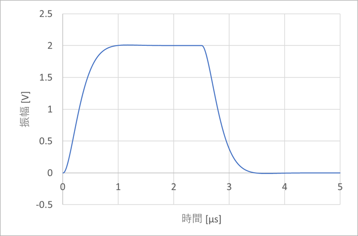
Figure 9 shows the response waveform of the output of the circuit in Figure 8 when a square wave is applied to the input. Figure 9(a) has R1=0, i.e. G=1, and Figure 9(b) has G=2.
For G=1 there is a slight overshoot on the rise (fall).
This overshoot may not be desirable when used for power supplies.
The reason for this difference will be explained next time.
next time,
Basic characteristics of operational amplifiers
Feedback loop characteristics
Operation when load capacity is applied
Solution for stabilization
etc.
Footnote 1:
Expressing 1/2 in decibels, 20log(1/2)=-6.02dB, but rounding off, we usually say -6dB.
1/10 is exactly -20dB.
"Digression 1"
An oscillator circuit is a classic example of a positive feedback circuit. Comparators and Schmitt trigger circuits are, in principle, positive feedback circuits.
Although it is not widely used today, nearly 100 years ago, the method of applying a positive feedback circuit to obtain gain with a small number of vacuum tubes was often used before and after the war. When I was a radio boy, I used to build regenerative radios using this method.
By adjusting the amount of positive feedback at a delicate position before oscillation, we were able to obtain high performance with a small number of parts. has been transmitted.
At that time, vacuum tubes were used for amplification. Then the vacuum tube was replaced by the transistor. Roughly speaking, vacuum tubes and transistors have similar functions. Today, general-purpose transistors cost less than 10 yen. I think the vacuum tubes at that time cost a few hundred yen as I recall. Considering the monetary value, isn't it a few thousand yen today?
Reducing the number of tubes used was therefore very important.
On a further digression, a super-regenerative circuit was invented that increased the amount of this positive feedback to the oscillation range and intermittently oscillated. It was used for transceivers in the old days, but it seems to be popular among amateur radio engineers even today.
What is Yuzo Usui's Specialist Column?
It is a series of columns that start from the basics, include themes that you can't hear anymore, themes for beginners, and also a slightly advanced level, all will be described in as easy-to-understand terms as possible.
Maybe there are other themes that interest you!