![]()
![]() Narrow down by specifying conditions
Narrow down by specifying conditions
現在1888件がヒットしています。check

As mentioned in "Switching Regulators - Part 1", numerical solutions can be obtained by Laplace transform and fast Fourier transform (FFT) analysis, but this time we prefer to solve "analytically" or "algebraically". think.
current equation
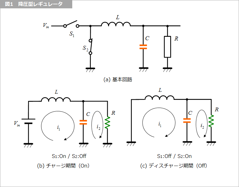
In the step-down regulator basic circuit of Figure 1(a), during the charge period (On) in Figure 1(b) S1 is On and S2 is Off, and in the reverse discharge period (Off) in Figure 1(c) , i1 and i2, and the approximation is shown in Figure 2.
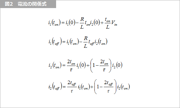
You can cycle On and Off for i1 and i2 to obtain the current transient response. The result is as shown in "Switching type regulator - Part 1".
steady state
In Fig. 3, the currents i1 and i2 at the time when the steady state has sufficiently reached are assumed to be i1(0) and i2(0), respectively. and i2 are the results.
At steady state, i1(Off) equals i1(0) and i2(Off) equals i2(0).
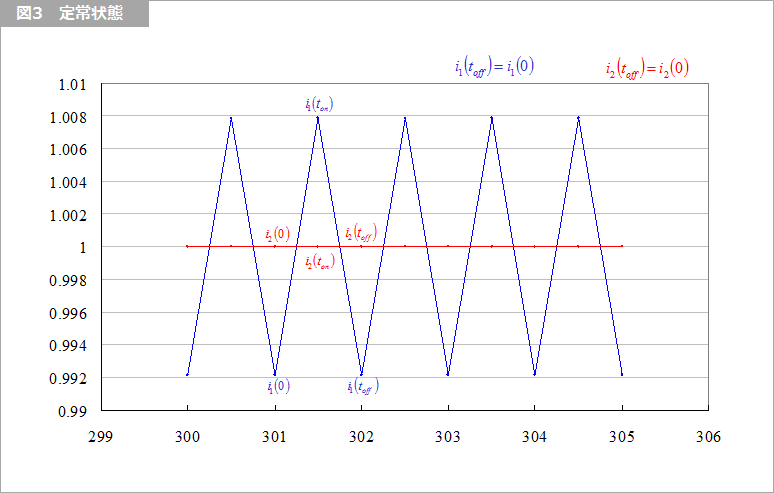
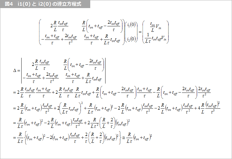
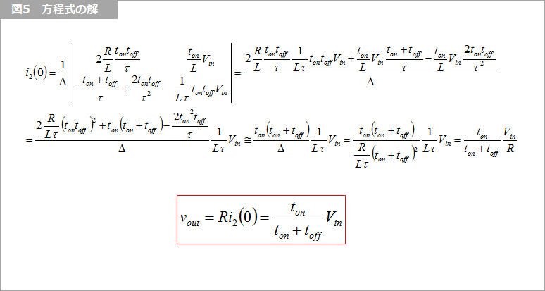
Figure 4 is the simultaneous equations obtained from Figure 2, and Figure 5 is the solution.
boost regulator
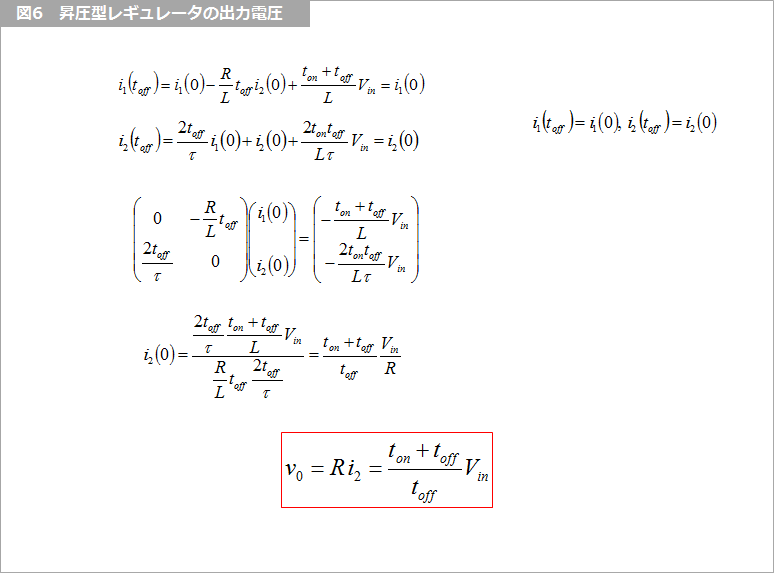
We will omit the details of the calculations for the boost regulator, but we can obtain the solution in Figure 6 by performing a similar analysis.
You can analyze circuits designed by SPICE and transients, i.e. numerical solutions, but you will need to solve them algebraically to design your own.
Recently, convenient tools have been provided, so analysis has become easy.
What is Yuzo Usui's Specialist Column?
It is a series of columns that start from the basics, include themes that you can't hear anymore, themes for beginners, and also a slightly advanced level, all will be described in as easy-to-understand terms as possible.
Maybe there are other themes that interest you!