- Semiconductor BusinessHOME
- Products and Services of Macnica,Inc.
-
technical information

-
Events and Seminars
- Handling Manufacturer
- Support
- Inquiry
- Click here to purchase products
- Semiconductor business e-mail magazine registration
![]()
![]() Narrow down by specifying conditions
Narrow down by specifying conditions
現在2183件がヒットしています。check

FFT of Excel that can be processed in real time
The FFT built into Excel has been introduced before.
Please refer to "FFT by Excel".
This built-in FFT took the form of batch processing and was not very user-friendly.
Therefore, I created an FFT that can be processed in real time, so I will introduce it.
Simple application of FFT
Fourier transform and FFT seem a little difficult, but let's use FFT with a simple example.
Figure 1 is a very simple integrator circuit with resistor R and capacitor C.
To obtain the response when a step waveform is applied to this circuit, the Laplace transform is used as an orthodox method.
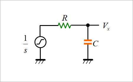
Since the impedance display of the capacitor is 1/sC and the step waveform is 1/s, it can be obtained relatively easily with the calculation shown in Figure 2.
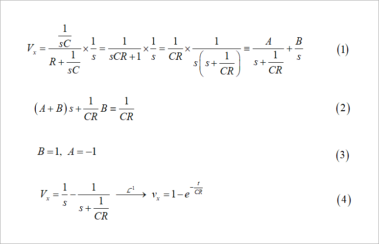
Partial fraction expansion on the right side of equation (1) is a bit cumbersome, but it's not that difficult once you get used to it. Using the identity of equation (2), compare the coefficients of each order of s and find A and B as in equation (3).
Equation (4) can be obtained from the obtained A and B, and the time response can be obtained by inverse Laplace transform.
See Figure 3 in "Laplace and Fourier Transforms".
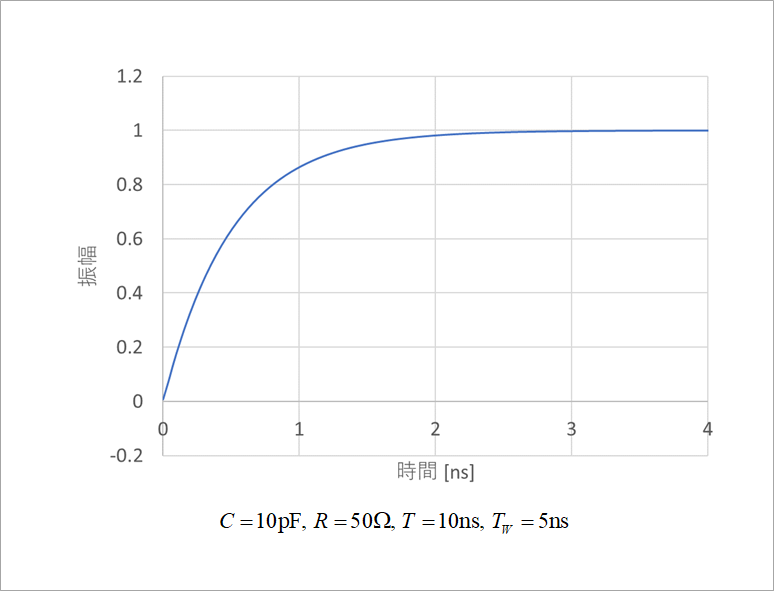
Figure 3 shows the calculation results.
It is easy to solve with the Laplace transform, but if it becomes a little complicated like an LCR circuit, the partial fraction expansion becomes complicated, and further operations such as dividing the case into oscillation mode and damping mode are required, so it becomes troublesome. I will come.
Here, the Laplace transform and the Fourier transform are very similar in form of integral, so if you replace s in the Laplace transform operator with jω and divide by the period, you get the Fourier transform.
Mathematically, they are different things, but you can think of them as relatives in terms of solving circuits. (Although it seems that mathematics experts will scold me)
See "Laplace and Fourier transforms".
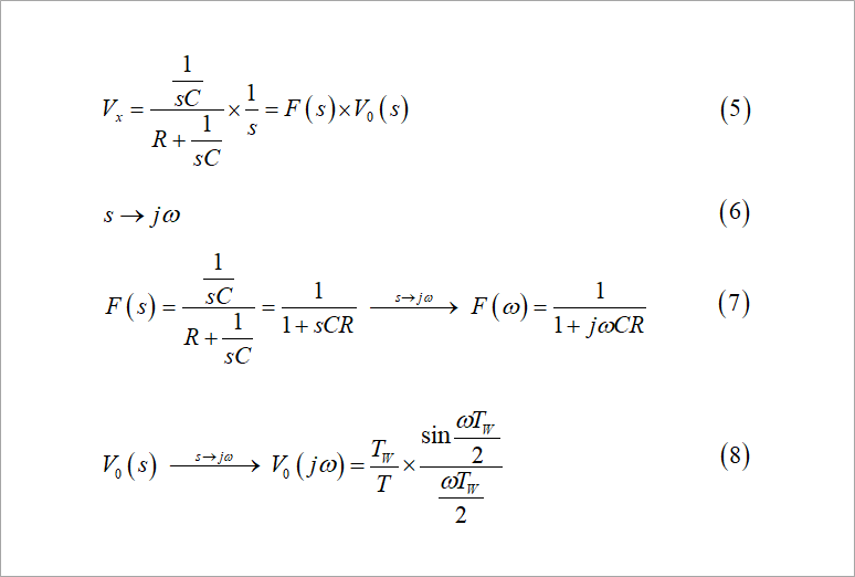
Consider Vx as the product of the transfer function F(s) and the signal source V0(s), as shown in equation (5) in Figure 4.
If s of F(s) is jω, then F(ω) is given by equation (7).
Since the Fourier transform considers the period of the signal source, it is expressed as shown in equation (8) in Figure 4.
FFT converts this frequency function into a time function.
The FFT of the real-time processing is uploaded below.
http://radioy.a.la9.jp/tool/tool.htm
or directly
http://radioy.a.la9.jp/tool/FFT256.xlsx
Two signal sources, a square wave and a trapezoidal wave, are prepared in advance.
A square wave is used to obtain the step response.
Enter the values for "C" and "R" of the CR integrator on the "sample" sheet.
Column E calculates the product of the transfer function F(jω) and the source V0(jω).
Quote the top cell of this ω function to "A2" on the "Waveform" sheet in the form of an absolute reference. In this example, it is "=sample!$E$4".
This time waveform is shown in Figure 5.
Select an appropriate CR value and signal source T and TW.
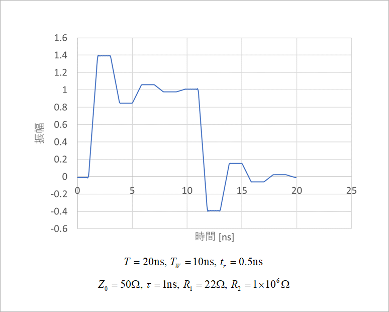
Next, find the reflected waveform of the distributed constant circuit.
The transfer function F of the distributed constant circuit is shown in Fig. 3 of "Vertical Sequence".
This formula is calculated with a sample in an Excel sheet.
Given the characteristic impedance Z0, the line length (delay time) τ, the driver output resistance R1, and the receiver termination resistance R2, the product of the transfer function and the signal source is calculated in the J column.
The signal source uses the trapezoidal wave from the "Signal Source" sheet.
Take the inverse Fourier transform of this function of ω.
Quote in the form of an absolute reference to "A2" on the "Waveform" sheet. That is, "=sample!$J$4".
With FFT, if the circuit response can be expressed as a frequency function, it can be converted to a time function by inverse Fourier transform using FFT.
When a circuit including complex LCR resonance is also obtained by Laplace transform, it was necessary to distinguish between damping mode and vibration mode, but it is easy to convert.
I plan to publish a sequel to this application of FFT in several installments.
I would appreciate it if you could give me your opinion on whether this circuit can solve the problem.
What is Yuzo Usui's Specialist Column?
It is a series of columns that start from the basics, include themes that you can't hear anymore, themes for beginners, and also a slightly advanced level, all will be described in as easy-to-understand terms as possible.
Maybe there are other themes that interest you!