- Semiconductor BusinessHOME
- Products and Services of Macnica,Inc.
-
technical information

-
Events and Seminars
- Handling Manufacturer
- Support
- Inquiry
- Click here to purchase products
- Semiconductor business e-mail magazine registration
![]()
![]() Narrow down by specifying conditions
Narrow down by specifying conditions
現在2191件がヒットしています。check
I think that many people have an image that is a little difficult to approach when it comes to queues. The circuit is divided into the input side and the output side, and the voltage and current are defined respectively. It can be called a two-terminal circuit because it has an input and an output, and it can also be called a four-terminal circuit because it has a common terminal for both input and output.
Here, we will focus on cascading rows that are effective when cascading circuits. Using this matrix, it is also easy to find the transfer function of the circuit.
Types and uses of matrices
Figure 1 is the matrix used in the circuit.
(a) Impedance matrix (Z matrix)
(b) Admittance matrix (Y matrix)
(c) Hybrid matrix (h matrix)
(d) Vertical sequence (F matrix)
There is also the S matrix, which is slightly different from these matrices.
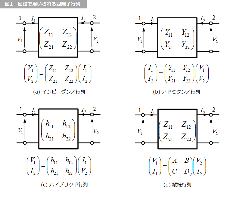
The impedance matrix is used when connecting circuits in series.
The admittance matrix is used for parallel connection of circuits.
And the hybrid matrix is the equivalent circuit of bipolar transistors.
A cascade is literally used to cascade circuits. Serial and tandem are sometimes confused, but tandem is an image of a two-story building and tandem is a train connection. Notice the direction of the current in Figure 1. Except for vertical rows, the direction of the flow into the circuit is positive (+) for both terminals 1 and 2. In a vertical row, terminal 1 is positive in the same direction as the others, but terminal 2 is positive in the opposite direction. Considering that the signal travels from left to right, it is more convenient to direct the current in the direction in which the signal travels.
vertical row
Now for the main subject, the vertical line. I studied the Z and Y matrices a lot when I was a student, but at least in my experience, I didn't have many opportunities to use them in practice. Since I stopped using bipolar transistors so much, I haven't had the chance to use the h-matrix.
The remaining vertical columns are practical and I use them more often than I learned when I was a student. It is very convenient when solving a normal circuit (lumped constant circuit) or a distributed constant circuit.
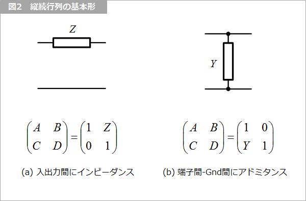
Basic form
As shown in Figure 2, we use the basic form in which impedance Z is connected between input and output, and admittance Y is connected between terminals and ground. We will stop at this here, and will explain it a little later with a concrete circuit.
Transfer function
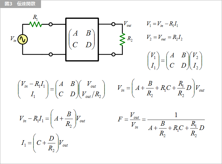
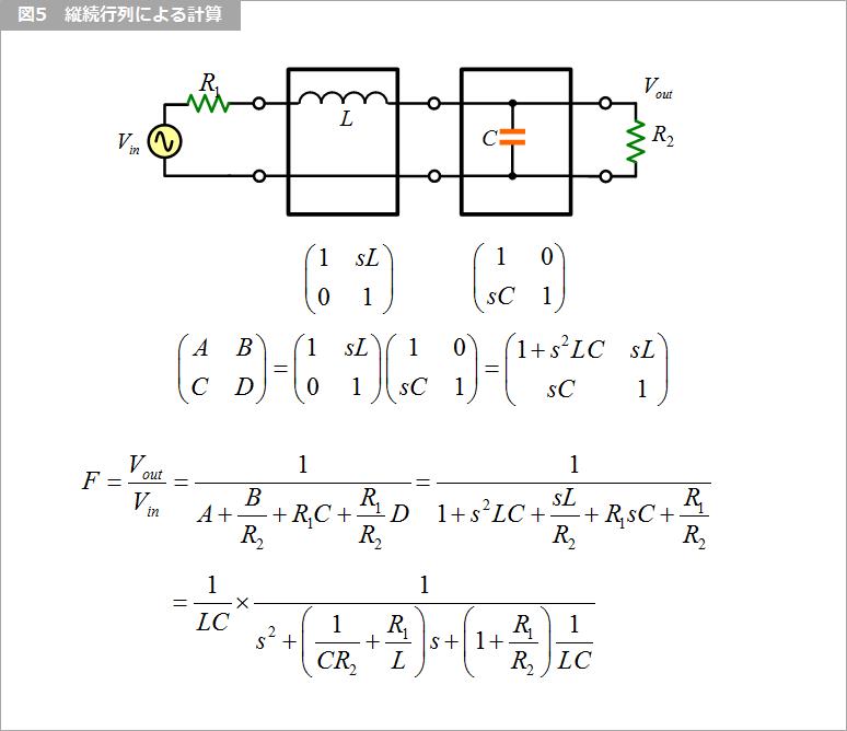
As shown in the circuit diagram in Figure 3, the transfer function F when the signal source resistor R1 and load resistor R2 are connected is obtained by converting the equation in Figure 3. The transfer function in Figure 3 can be obtained from the vertical series A, B, C, D and R1 and R2.
real example
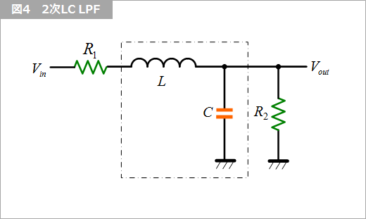
Find the transfer function of the second-order LC LPF (Low Pass Filter) in Figure 4.
Obtain the cascade coefficients of the basic form in Fig. 5 as shown in the figure, and obtain the entire cascade by matrix multiplication. By substituting these A, B, C, and D into the transfer function equation in Figure 3, the transfer function F can be obtained. I would like to talk about filter characteristics on another occasion.
What is Yuzo Usui's Specialist Column?
It is a series of columns that start from the basics, include themes that you can't hear anymore, themes for beginners, and also a slightly advanced level, all will be described in as easy-to-understand terms as possible.
Maybe there are other themes that interest you!