- Semiconductor BusinessHOME
- Products and Services of Macnica,Inc.
-
technical information

-
Events and Seminars
- Handling Manufacturer
- Support
- Inquiry
- Click here to purchase products
- Semiconductor business e-mail magazine registration
![]()
![]() Narrow down by specifying conditions
Narrow down by specifying conditions
現在2147件がヒットしています。check

This article describes how to design a step-down DC/DC converter circuit using LTpowerCAD.
Switching regulator circuits can be designed with manual calculations, but using LTpowerCAD has the following advantages.
・A circuit diagram can be completed just by entering the power supply specifications (fine adjustment may be required)
・Depending on the specifications, you can check the parts that you need to be careful about when using the device.
・It is possible to check the phase margin, which cannot be done by manual calculation.
Let's take a look at these benefits step by step.
Additionally, seminars on how to use LTpowerCAD related to this article are scheduled to be held in June and December every year.
If you would like to participate, we will start accepting applications approximately one month in advance, so please wait.
Install LTpowerCAD
Download the installer from the Analog Devices LTpowerCAD page.
The link to the page is here (moves to the page of Analog Devices, Inc.).
You can download a zip file (LTpowerCADII.zip) by clicking the part that says Download LTpowerCAD. Click setup.exe in the unzipped ZIP file to install.
After installation, in order to update to the latest version, click OK when asked "Do you want to Sync/Release?"
If you are not asked, click the LTpowerCAD icon on the desktop to run it.
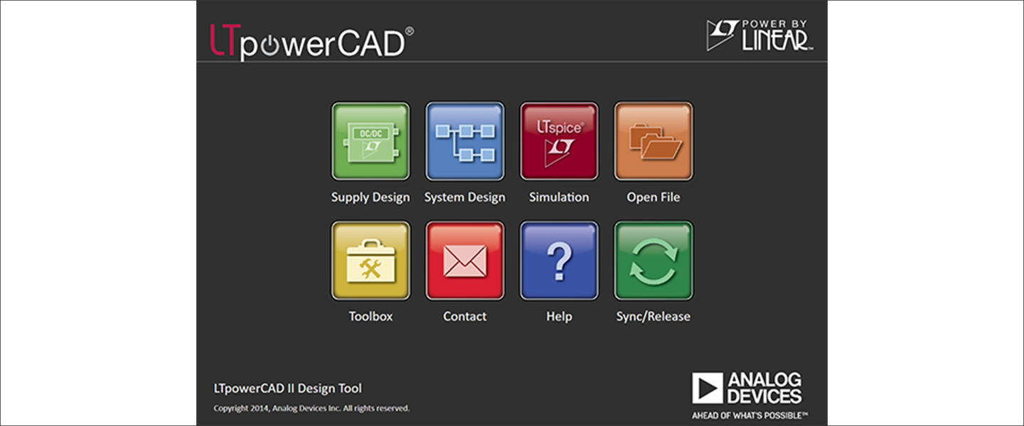
This will open the menu screen shown in Figure 1. Click "Sync/Release" at the bottom right of the menu to execute the version upgrade.
Power supply circuit specification input and device selection
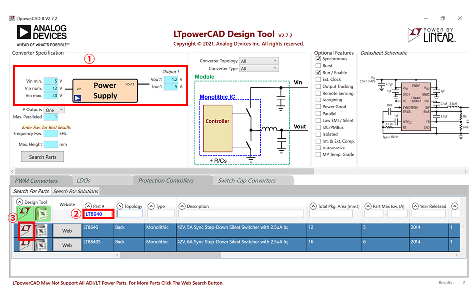
Click "Supply Design" on the upper left of the menu screen in Fig. 1 to open the parts search menu screen in Fig. 2.
First, enter the specifications of the switching regulator in the Converter Specification (red frame ①).
Input voltage conditions are Vin min.=5V, Vin nom.=12V, Vin max.=20V
I entered Vout1=1.2V, Iout1=5A as output conditions.
Next, enter the part “LT8640” to be used in Part# (red frame ②). Then "LT8640" will be searched and displayed at the top of the list.
(If it is not displayed, it is a product for which LTpowerCAD does not have a sheet for calculation.)
Finally, click the red frame ③ in the Design Tool on the left to open the LT8640 Design Tool.
design tools
Confirmation of basic peripheral constants (Power Stage Design sheet)
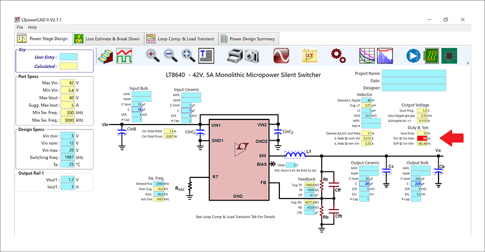
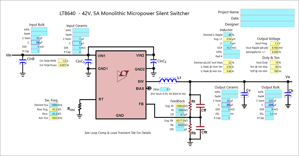
Figure 3 shows the design tool screen. A circuit diagram that meets the required specifications is shown.
Blue cells can be freely entered. Yellow cells are part specs or calculation results.
If the calculation results are all yellow, the schematic is usable.
If you look closely, you can see that there is one red cell in the arrow area, which deviates from the LT8640 specifications.
Since it cannot be used as it is, adjustment is necessary.
Deviating from the specifications may cause an error in the calculation results
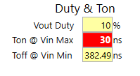
Figure 5 is an enlarged view of the red cell. It is said that Ton@Vin Max is out of specification at 30ns.
This means that the Minimum On Time specified by the LT8640 is 30nsec under Vin Max. conditions, which is out of spec.
According to the LT8640 data sheet spec, Max.
Regarding Minum On Time, please refer to Macnica Service's power supply dock column ``Part 3: Increasing the input voltage causes the output voltage to become unstable...'' for an example of when the Minum On Time deviates from the regulations. If you would like to learn more, we recommend that you attend the Power Supply Design Seminar.
Review of conditions
I will consider two ways as a review of the conditions.
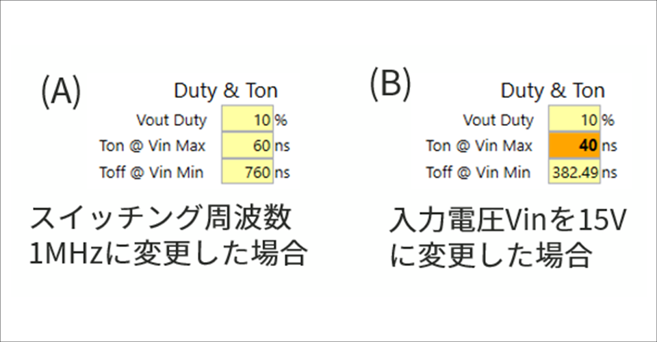
(A) changes the frequency from about 2MHz to 1MHz
(B) changes the maximum input voltage Vin Max. from 20V to 15V
The modified calculation results are shown in Fig. 5. By changing the switching frequency to 1MHz in (A), Ton became 60nsec, which is within the specified range. By changing the maximum input voltage of (B) to 15V, it is improved to 40nsec, but it is not within the specified range of Ton Max.=50nsec.
As a result, this time, the circuit diagram of the Power Stage part is determined by setting the switching frequency to 1MHz (Fig. 6).
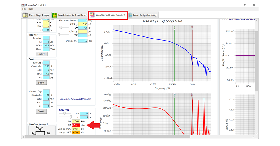
Phase/gain margin confirmation (Loop Comp. & Load Transient sheet)
Next, change the sheet from "Power Stage Design" to the "Loop Comp. & Load Transient" sheet framed in red and check the constant setting of the compensation circuit.
When you check it, there is a red cell in the arrow part. It seems that the phase margin is insufficient.
Review of compensation circuit
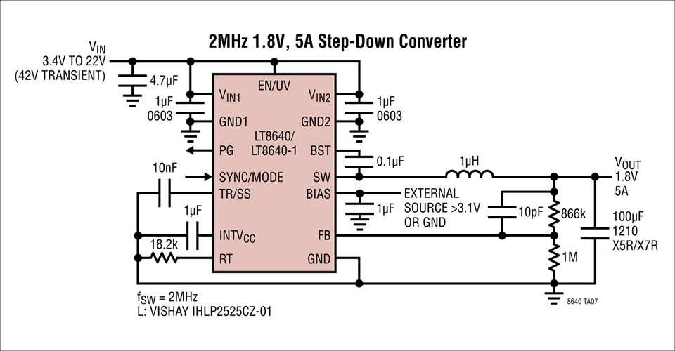
To review the compensation circuit, review the constants with reference to the circuit diagram in the data sheet. Let's compare it with the circuit diagram for the 1.8V output setting, which is close to the desired output of 1.2V (Figure 8).
There was a difference in the Cff (capacitor next to the FB resistor on the top side) and the output capacitor between the completed circuit diagram (Fig. 6) and the datasheet circuit diagram.
Try changing the values in the Loop Comp. & Load Transient sheet to the values in the datasheet in Figure 8.
・Cff constant change from 4.7pF to 10pF
・Ooutput Bulk 220uF → Delete
・Output ceramic 20uF → 100uF
Then, the phase margin improved from about 8.6 degrees to about 44.9 degrees.
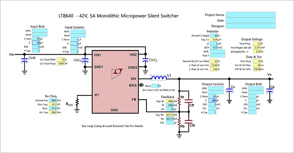
Since I want a phase margin of 45 degrees or more, I changed the capacity of the output capacitor to 180uF.
As a result, the phase margin improved to about 50 degrees.
Summary
Now all the errors (red cells) are gone and the circuit is completed with LTpowerCAD (Figure 9).
This time, we did not finish creating the circuit diagram just by entering the specifications, but we were able to confirm the following benefits of using LTpowerCAD.
1. You can create circuit diagrams in a shorter time than doing manual calculations.
2. Automatically check Minimum On Time, which is often overlooked during design
3. It is possible to adjust the phase margin, which cannot be done by manual calculation.
We hope that you will use LTpowerCAD to eliminate circuit design mistakes and improve design efficiency.
If you would like to learn more about LTpowerCAD, we also hold seminars in June and December.
We look forward to your participation.
Click here for recommended seminars/workshops
[Online Seminar] Let's design power supply circuits efficiently using tools! <Free>
[Online Seminar] Analog Solution Power Supply Design Seminar <free>
[Online Seminar] Analog Solution Thermal Design Seminar <Free>
Click here for recommended articles/materials
Click here to purchase products
Inquiry
If you have any questions regarding this article, please contact us below.
Analog Devices Manufacturer Information Top
To return to the Analog Devices manufacturer information top page, please click below.